


11-8
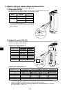
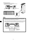
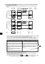
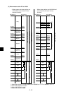
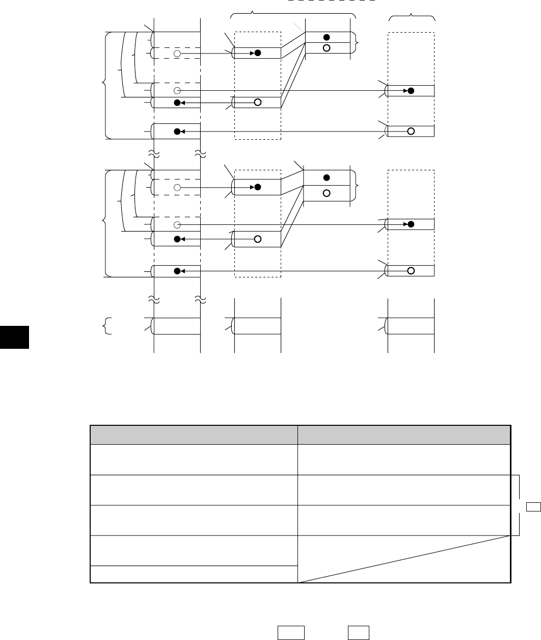
(2) In case that setting the data link (save memory function) when the master station and all
slave stations are JW-21MN's.
Memory addresses inside control module of slave station continue in order of receiving and
sending.
: Send
: Receive
* Number of receiving bytes of slave station (h1 to hn, i1 to in)
Select self-setting or "same as number of sending bytes (c1 to cn, d1 to dn)" according to
parameter (007720 to 007723) of slave station.
Note: When installing JW-21MN without 30Hn mark or 30H mark into JW20/JW20H, number
of receiving bytes of each slave station is the same as number of sending bytes.
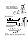
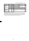
- Set the relay link area, the register link area, and the flag area within the settings range of page
11-11, 12 and 23. Be careful not to double any address allocation of these.
- Set a0 to en, h1 to in above for parameters of master station and slave station (see page 11-5, 6
and 22) and set f1/fn/g1/gn marked "*" by module No. switch of the JW-21MN (see page 11-2).
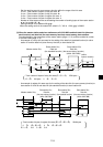
(Within a
total of
512 bytes)
Slave station 01
(8)
(Data memory)
Master station 00
(8)
(Data memory)
*
*
*
*
*
Flag
area
Slave station n
(Data memory)
to
(Within JW-21MN)
(Within control
module)
- Omitted a memory map
inside control module.
(Within
64 bytes
in total)
Relay link area
(Within a total of 256 bytes)
Register link area
(Within a total of 2048 bytes)
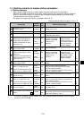
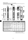
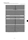
Parameter for setting in master station
Top address of relay link area a0, a1 to an
Top address of register link area b0, b1 to bn
Number of sending bytes of relay link area
c0, c1 to cn
Number of sending bytes of register link
area d0, d1 to dn
Top address of flag area (master station) e0.
Parameter for setting in slave station
Top address of flag area (slave station) e1 to
en
Number of receiving bytes of relay link area
h1 to hn
Number of receiving bytes of register link
area i1 to in
V2