


Series 24-HP Instruction Manual Chapter 1 Introduction
IM-24-HP 1-7
Pressure Measurement
Innova-Mass Flow Meters incorporate a solid-state pressure transducer
isolated by a 316 stainless steel diaphragm. The transducer itself is mi-
cro-machined silicon, fabricated using integrated circuit processing tech-
nology. A nine-point pressure/temperature calibration is performed on
every sensor. Digital compensation allows these transducers to operate
within a 0.3% of full scale accuracy band within the entire ambient tem-
perature range of -4°F to 140°F. Thermal isolation of the pressure trans-
ducer ensures the same accuracy across the allowable process fluid tem-
perature range of -40°F to 750°F.
Flow Meter Configurations
Innova-Mass™ Vortex Mass Flow Meters are available in two
configurations:
• Series 240 in-line flow meter (replaces a section of the pipeline)
• Series 241 insertion flow meter (requires a “cold” tap or a “hot” tap
into an existing pipeline)
Both the in-line and insertion configurations are similar in that they both
use identical electronics and have similar sensor heads. Besides installa-
tion differences, the main difference between an in-line flow meter and
an insertion flow meter is their method of measurement.
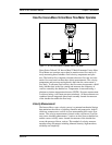
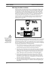
For an in-line vortex flow meter, the shedder bar is located across the en-
tire diameter of the flow body. Thus, the entire pipeline flow is included
in the vortex formation and measurement. The sensing head, which di-
rectly measures velocity, temperature and pressure is located just down-
stream of the shedder bar.
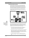
Insertion vortex flow meters have a shedder bar located across the di-
ameter of a short tube. The velocity, temperature and pressure sensor are
located within this tube just downstream of a built-in shedder bar. This
entire assembly is called the insertion sensing head. It fits through any
entry port with a 1.875 inch minimum internal diameter.
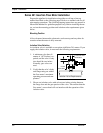
The sensing head of an insertion vortex flow meter directly monitors the
velocity at a point in the cross-sectional area of a pipe, duct, or stack (re-
ferred to as “channels”). The velocity at a point in the pipe varies as a
function of the Reynolds number. The insertion vortex flow meter com-
putes the Reynolds number and then computes the total flow rate in the
channel. The output signal of insertion meters is the total flow rate in the
channel. The accuracy of the total flow rate computation depends on ad-
herence to the piping installation requirements given in Chapter 2. If ad-
herence to those guidelines cannot be met, contact the factory for specific
installation advice.