


Series 24-HP Instruction Manual Chapter 2 Installation
IM-24-HP 2-23
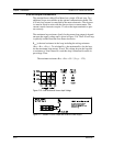
Alarm Output Connections
One alarm output (Alarm 1) is included on the standard Innova-Mass™
Flow Meter. Two or more alarms (Alarm 2 and Alarm 3) are included on
the optional communication board. The alarm output optical relays are
normally-open single-pole relays. The relays have a nominal 200 volt/160
ohm rating. This means that each relay has a nominal on-resistance of 160
ohms and the largest voltage that it can withstand across the output termi-
nals is 200 volts. However, there are current and power specifications that
must be observed. The relay can conduct a current up to 40 mA and can
dissipate up to 320 mW. The relay output is isolated from the meter elec-
tronics and power supply. When the alarm relay is closed, the current
draw will be constant. Make sure to size R
load
appropriately.
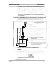
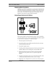
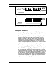
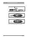
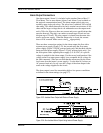
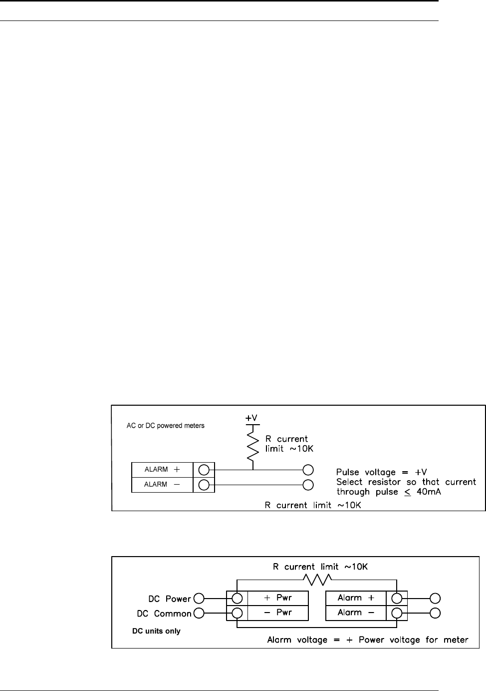
There are three connection options for the alarm output–the first with a
separate power supply (Figure 2-23), the second using the flow meter
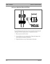
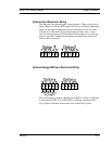
power supply (Figure 2-24)(DC powered units only) and the third with the
meter provided power supply (Figure 2-25)(AC powered units only). Use
the first option with a separate power supply (5 to 36 VDC) if a specific
voltage is needed for the alarm output. Use the second configuration if the
voltage at the flow meter power supply is an acceptable driver voltage for
the load connected. (Take into account that the current used by the alarm
load comes from the meter’s power supply). Use the third if you have an
AC powered unit only. In any case, the voltage of the alarm output is the
same as the voltage supplied to the circuit.
The alarm output is used for transmitting high or low process conditions
as defined in the alarm settings (see page 3-7).
Figure 2-23. Isolated Alarm Output with External Power Supply
Figure 2-24. Non-Isolated Alarm Output Using Internal Power Supply