


Chapter 2 Installation Series 24-HP Instruction Manual
2-8 IM-24-HP
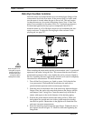
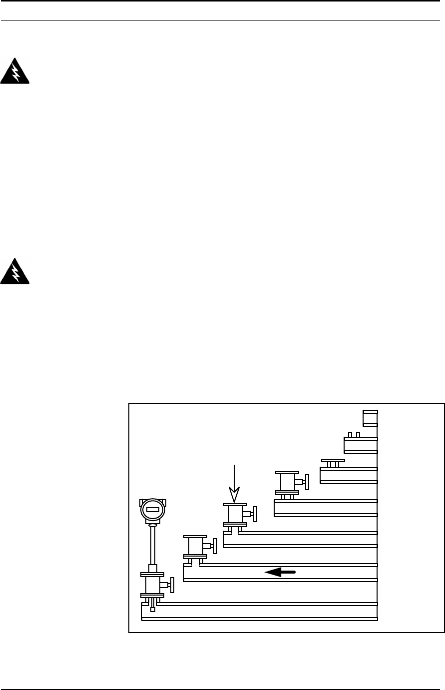
Hot Tap Guidelines
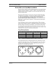
Refer to a standard code for all pipe tapping operations. The following
tapping instructions are general in nature and intended for guideline pur-
poses only.
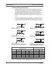
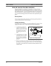
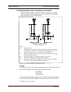
1. Confirm that the installation site meets the minimum upstream and
downstream pipe diameter requirements.
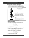
2. Weld a two inch mounting adapter on the pipe. Make sure the mount-
ing adapter is within ± 5° perpendicular to the pipe centerline (see
previous page). The pipe opening must be at least 1.875 inches in di-
ameter.
3. Connect a two inch process connection on the mounting adapter.
4. Connect an isolation valve on the process connection. The valve’s
full open bore must be at least 1.875 inches in diameter.
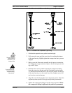
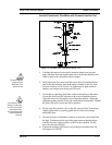
5. Hot tap the pipe.
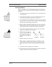
6. Close the isolation valve. Run a static pressure check on the welds. If
pressure loss or leaks are detected, repair the joint and re-test.
7. Connect the flow meter to the isolation valve.
8. Calculate the sensor probe insertion depth as described on the follow-
ing pages. Insert the sensor probe assembly into the pipe.
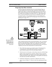
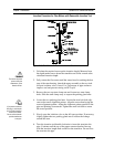
Check upstream and
downstream piping
requirements
Weld mounting
adapter
Connect process
connection
(flange or NPT)
Connect
isolation valve
Test for leaks,
purge pipe
Hot tap pipe
Connect meter to
valve, calculate
insertion depth,
install flow meter
FLOW
Figure 2-5. Hot Tap Sequence
Warning!
Hot tapping must be
performed by a trained pro-
fessional. US. regulations of-
ten require a hot tap permit.
The manufacturer of the hot
tap equipment and/or the con-
tractor performing the hot tap
is responsible for providing
proof of such a permit.
Warning!
All flow meter connections,
isolation valves and fittings for
hot tapping must have the
same or higher pressure rat-
ing as the main pipeline.