


Series 24-HP Instruction Manual Chapter 4 Troubleshooting & Repair
IM-24-HP 4-3
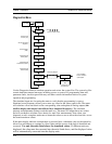
• Lvl = threshold level. If the Low Flow Cutoff in the calibra-
tion menu is set above this value, the meter will read zero flow.
The Lvl level can be checked at no flow. At no flow, the Lvl
must be below the Low Flow Cutoff setting or the meter will
have an output at no flow.
• Adj. Flilter = adjustable filter. Displays the filtering in deci-
bels. Normally reads zero. If this value is consistently -5 or
-10, for example, the Ck or density setting may be wrong.
• O,I = factory use only.
• Pulse Out Queue = Pulse output queue. This value will accu-
mulate if the totalizer is accumulating faster than the pulse out-
put hardware can function. The queue will allow the pulses to
“catch up” later if the flow rate decreases. A better practice is
to slow down the totalizer pulse by increasing the value in the
(unit)/pulse setting in the totalizer menu.
• TOF, G, f = factory use only.
• Sig. Rev = Signal board hardware and firmware revision.
• Miro Rev = Microprocessor board hardware and firmware re-
vision.
• AD, R, T, F, PT, V = factory use only.
• SPR Err, Rcv, Sent = factory use only.
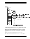
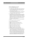
Column Two Hidden Diagnostics Values
• 4-20(1) Zero = Analog counts to calibrate zero on analog out-
put 1.
• 4-20(1) FScale = Analog counts to cal. full scale on analog
output 1.
• 4-20(2) Zero = Analog counts to calibrate zero on analog out-
put 2.
• 4-20(2) FScale = Analog counts to cal. full scale on analog
output 2.
• 4-20(3) Zero = Analog counts to calibrate zero on analog out-
put 3.
• 4-20(3) FScale = Analog counts to cal. full scale on analog
output 3.
• Alarm (1) Test = Used as a test to verify that the alarm circuit
is functioning. When low is selected the alarm will initiate a
low alarm on the output. When High is selected it will give a
high alarm on the output.