


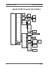

Appendix E MODBUS Commands Series 24-HP Instruction Manual
E-6 IM-24-HP
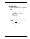
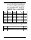
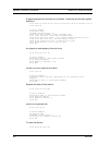
Discrete Input Definitions
The status of the three alarms may be monitored via the Modbus Read Discrete
Input command (function code 02). The value returned indicates the state of the
alarm, and will be 1 only if the alarm is enabled and active. A zero value is trans-
mitted for alarms that are either disabled or inactive,
Registers Variable Function Code Address
10001 Alarm #1 state 02 0
10002 Alarm #2 state 02 1
10003 Alarm #3 state 02 2
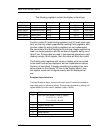
Control Register Definitions
The only writeable registers in this implementation are the Reset
Exception Status, Reset Meter and Reset Totalizer functions, which
are implemented as ”coils” which may be written with the Write
Single Coil command (function code 05) to address 8 through 10,
respectively, (register #00009 through #00011). The value sent with
this command must be either 0x0000 or 0xff00, or the meter will re-
spond with an error message; the totalizer will be reset or exception
status cleared only with a value of 0xff00.
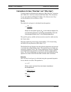
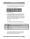
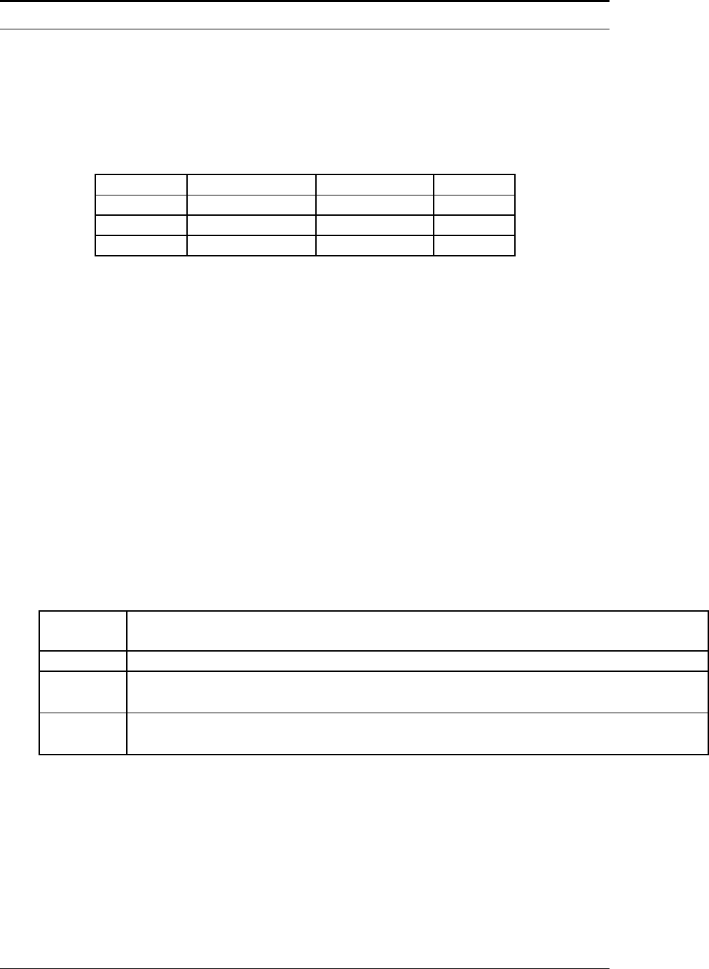
Error Responses
If an error is detected in the message received by the unit, the function code
in the response is the received function code with the most significant bit set,
and the data field will contain the exception code byte, as follows:
If the first byte of a message is not equal to the unit’s Modbus ad-
dress, if the unit detects a parity error in any character in the re-
ceived message (with even or odd parity enabled), or if the mes-
sage CRC is incorrect, the unit will not respond.
Exception
Code Description
01 Invalid function code — function code not supported by device
02 Invalid data address — address defined by the start address and number of registers
is out of range
03 Invalid data value — number of registers = 0 or >125 or incorrect data with the Write
Single Coil command