


Series 24-HP Instruction Manual Chapter 2 Installation
IM-24-HP 2-5
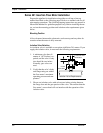
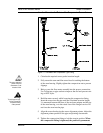
Flange-Style Flow Meter Installation
Install the flange-style meter between two conventional pipe flanges of
the same nominal size as the flow meter. If the process fluid is a liquid,
make sure the meter is located where the pipe is always full. This may re-
quire locating the meter at a low point in the piping system. Note: Vortex
flow meters are not suitable for two-phase flows (i.e., liquid and gas mix-
tures). For horizontal pipelines having a process temperature above 300°
F, mount the meter at a 45 or 90-degree angle to avoid overheating the
electronics enclosure. To adjust the viewing angle of the enclosure or dis-
play/keypad, see page 2-17.
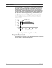
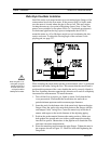
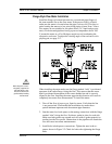
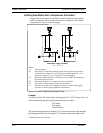
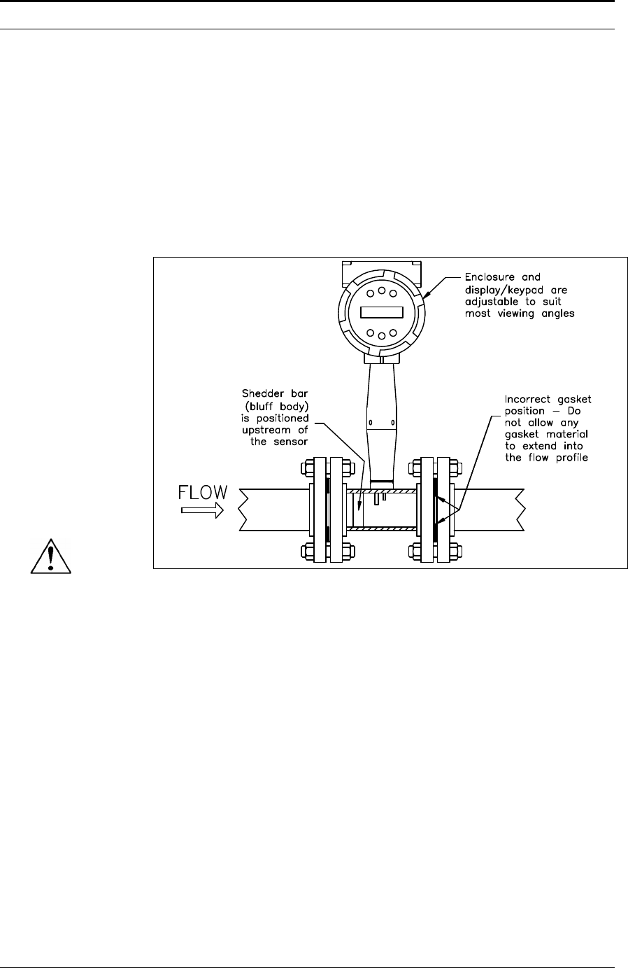
Figure 2-4. Flange-Style Flow Meter Installation
When installing the meter make sure the flange marked “inlet” is positioned
upstream of the outlet flange, facing the flow. This ensures that the sensor
head is positioned downstream of the vortex shedder bar and is correctly
aligned to the flow. Installing the meter opposite this direction will result in
completely inaccurate flow measurement. To install the meter:
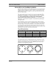
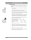
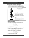
1. Turn off the flow of process gas, liquid or steam. Verify that the line
is not pressurized. Confirm that the installation site meets the re-
quired minimum upstream and downstream pipe diameters.
2. Seat the meter level and square on the mating connections with the flange
marked “inlet” facing the flow. Position a gasket in place for each side.
Make sure both gaskets are smooth and even with no gasket material ex-
tending into the flow profile. Obstructions in the pipeline will disturb the
flow and cause inaccurate measurements.
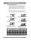
3. Install bolts in both process connections. Tighten the nuts in the se-
quence shown in Figure 2-2. Check for leaks after tightening the flange
bolts.
Caution!
When using toxic or corro-
sive gases, purge the line
with inert gas for a mini-
mum of four hours at full
gas flow before installing
the flow meter.