


Chapter 2 Installation Series 24-HP Instruction Manual
2-24 IM-24-HP
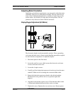
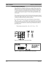
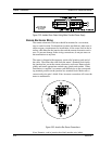
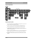
Figure 2-25. Isolated Alarm Output Using Meter Provided Power Supply
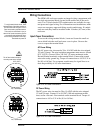
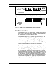
Remote Electronics Wiring
The remote electronics enclosure should be mounted in a convenient,
easy to reach location. For hazardous location installations, make sure to
observe agency requirements for installation. Allow some slack in the in-
terface cable between the junction box and the remote electronics enclo-
sure. To prevent damage to the wiring connections, do not put stress on
the terminations at any time.
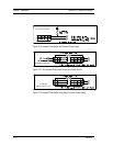
The meter is shipped with temporary strain relief glands at each end of
the cable. Disconnect the cable from the meter’s terminal block inside
the junction box–not at the remote electronics enclosure. Remove both
glands and install appropriate conduit entry glands and conduit. When
installation is complete, re-connect each labeled wire to the correspond-
ing terminal position on the junction box terminal block. Make sure to
connect each wire pair’s shield. Note: incorrect connection will cause the
meter to malfunction.
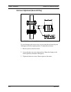
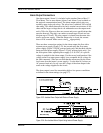
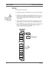
GND
PWR
Sensor V1
Sensor V2
Shield
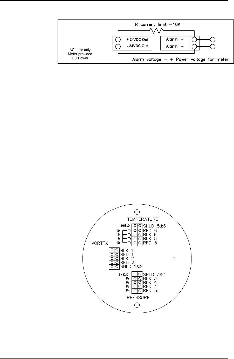
Figure 2-26. Junction Box Sensor Connections
Note: Numeric code in junction box label matches wire labels.