


Chapter 2 Installation Series 24-HP Instruction Manual
2-2 IM-24-HP
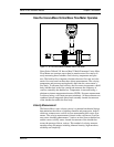
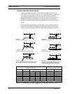
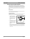
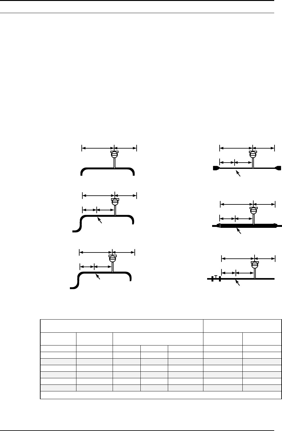
Unobstructed Flow Requirements
Select an installation site that will minimize possible distortion in the
flow profile. Valves, elbows, control valves and other piping components
may cause flow disturbances. Check your specific piping condition
against the examples shown below. In order to achieve accurate and re-
peatable performance install the flow meter using the recommended
number of straight run pipe diameters upstream and downstream of the
sensor.
Note: For liquid applications in vertical pipes, avoid installing with flow
in the downward direction because the pipe may not be full at all points.
Choose to install the meter with flow in the upward direction if possible.
Flow meter
A B
Example 1.
One 90° elbow before meter
C'
Flow meter
A B
C
Flow conditioner
(if used)
Example 2.
Two 90° elbows before meter in one plane
C'
Flow meter
A B
C
Flow conditioner
(if used)
Example 3.
Two 90° elbows before meter out of plane (if three
90° bends present, double recommended length)
Flow meter
A B
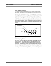
Example 4.
Reduction before meter
C' C
Flow conditioner
(if used)
Flow meter
A B
C' C
Flow conditioner
(if used)
Example 5.
Expansion before meter
Example 6.
Regulator or valve partially closed before meter
(If valve is always wide open, base length
requirements on fitting directly preceding it)
Flow meter
A B
C' C
Flow conditioner (if used)
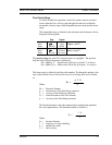
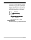
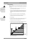
Minimum Required
Upstream Diameters
Minimum Required
Downstream Diameters
No Flow
Conditioner
With Flow Conditioner
No Flow
Conditioner
With Flow
Conditioner
Example A A C C´ B B
1 10 D N/A N/A N/A 5 D 5 D
2 15 D 10 D 5 D 5 D 5 D 5 D
3 25 D 10 D 5 D 5 D 10 D 5 D
4 10 D 10 D 5 D 5 D 5 D 5 D
5 20 D 10 D 5 D 5 D 5 D 5 D
6 25 D 10 D 5 D 5 D 10 D 5 D
D = Internal diameter of channel. N/A = Not applicable
Figure 2-1. Recommended Pipe Length Requirements for Installation, Series 240 and 241