


Chapter 2 Installation Series 24-HP Instruction Manual
2-14 IM-24-HP
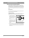
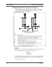
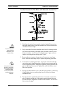
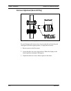
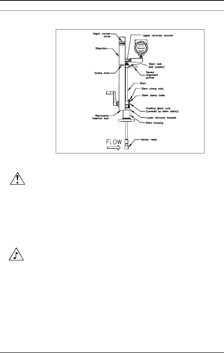
Insertion Procedure for Flow Meters with Removable Insertion Tool
Figure 2-10. Flow Meter with Removable Insertion Tool
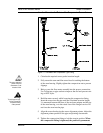
1. Calculate the required sensor probe insertion length. Measure from
the depth marker arrow down the stanchion and scribe a mark at the
calculated insertion depth.
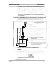
2. Fully retract the flow meter until the sensor head is touching the bot-
tom of the stem housing. Attach the meter assembly to the two inch
full-port isolation valve, if used. Use Teflon tape or pipe sealant to
improve seal and prevent seizing on NPT style.
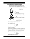
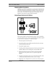
3. Remove the two top stem clamp nuts and loosen two stem clamp
bolts. Slide the stem clamp away to expose the packing gland nuts.
4. Loosen the two packing gland nuts. Loosen the stem lock bolt adja-
cent to the sensor alignment pointer. Align the sensor head using the
sensor alignment pointer. Adjust the alignment pointer parallel to the
pipe and pointing downstream. Tighten the stem lock bolt to secure
the sensor position.
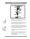
5. Slowly open the isolation valve to the full open position. If necessary,
slightly tighten the two packing gland nuts to reduce the leakage
around the stem.
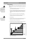
6. Turn the insertion tool handle clockwise to insert the stem into the
pipe. Continue until the top of the upper retractor bracket lines up
with the insertion length mark scribed on the stanchion. Do not force
the stem into the pipe.
Caution!
The sensor alignment
pointer must point
downstream, in the
direction of flow.
Note
If line pressure is above
500 psig, it could require
up to 25 ft lb of torque to
insert the flow meter.
Do not confuse this with
possible interference
in the pipe.