


Series 24-HP Instruction Manual Chapter 2 Installation
IM-24-HP 2-15
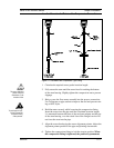
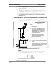
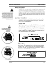
7. Tighten the packing gland nuts to stop leakage around the stem. Do not
torque over 20 ft-lbs.
8. Slide the stem clamp back into position. Torque stem clamp bolts to 15
ft-lbs. Replace the stem clamp nuts and torque to 10-15 ft-lbs.
9. To separate the insertion tool from the flow meter, remove four socket
head cap bolts securing the upper and lower retractor brackets. Remove
the insertion tool.
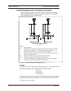
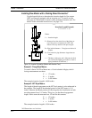
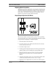
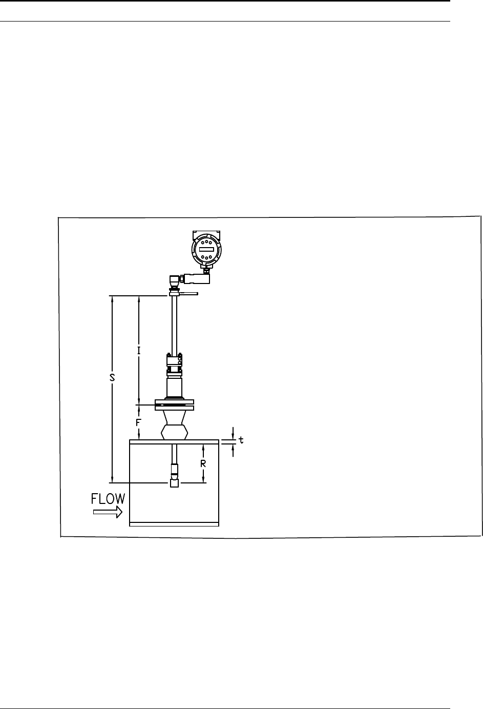
Installation of Meters with Packing Gland Connection (No Insertion Tool)*
Use the following formula to determine insertion depth for meters with a
packing gland connection (NPT and flanged) without an insertion tool.
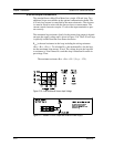
Insertion Length Formula
I = S – F – R – t
Where:
I = Insertion length.
S = Stem length – the distance from the cen-
ter of the sensor head to the base of the
enclosure adapter (S = 29.47 inches for
standard probes; S = 41.47 inches for
12 inch extended probes).
F = Distance from the raised face of the
flange or top of NPT stem housing to
the outside of the pipe wall.
R = Pipe inside diameter ÷ 2 for pipes ten
inches & smaller.
R = Five inches for pipe diameters larger than ten
inches.
t = Thickness of the pipe wall. (Measure the disk
cut-out from the tapping procedure or check a
piping handbook for thickness.)
Figure 2-11. Insertion Calculation (Meters without Insertion Tool)
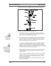
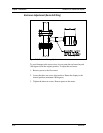
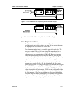
Example:
To install a Series 241 Flow Meter with a standard probe (S = 29.47) into
a 14 inch schedule 40 pipe, the following measurements are taken:
F = 3 inches
R = 5 inches
t = 0.438 inches
The example insertion length is 21.03 inches.
*All dimensions are in inches.