


Series 24-HP Instruction Manual Table of Contents
IM-24-HP 0-5
Figures
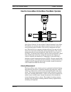
1-1. In-Line Vortex Multi-Parameter Mass Flow Meter ............... 1-3
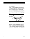
1-2. Measurement Principle of Vortex Flow Meters ..................... 1-4
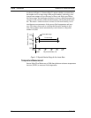
1-3. Reynolds Number Range of the Innova-Mass........................ 1-6
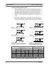
2-1. Recommended Pipe Length Required for Installation ........... 2-2
2-2. Flange Bolt Torquing Sequence ............................................. 2-3
2-3. Wafer-Style Flow Meter Installation...................................... 2-4
2-4. Flange-Style Flow Meter Installation..................................... 2-5
2-5. Hot Tap Sequence................................................................... 2-8
2-6. Insertion Calculation (Compression Type) .......................... 2-10
2-7. Flow Meter with Compression Type Fitting ........................ 2-11
2-8. Insertion Calculation (Meters with Insertion Tool).............. 2-12
2-9. Flow Meter with Permanent Insertion Tool ......................... 2-13
2-10. Flow Meter with Removable Insertion Tool ........................ 2-14
2-11. Insertion Calculation (Meters without Insertion Tool)......... 2-15
2-12. Display/Keypad Viewing Adjustment.................................. 2-17
2-13. Enclosure Viewing Adjustment............................................ 2-18
2-14. AC Power Connections ........................................................ 2-19
2-15. DC Power Connections ........................................................ 2-19
2-16. Load Resistance Versus Input Voltage................................. 2-20
2-17. Isolated 4-20 Output with External Power Supply............... 2-20
2-18. Non-Isolated 4-20 Output using Input Power Supply .......... 2-21
2-19. Isolated 4-20 Output using Meter Power Supply (AC only) 2-21
2-20. Isolated Pulse Output using External Power Supply............ 2-22
2-21. Non-Isolated Pulse Output using Input Power Supply......... 2-22
2-22. Isolated Pulse Output using Meter Power Supply (AC only)2-22
2-23. Isolated Alarm Output using External Power Supply .......... 2-23
2-24 Non-Isolated Alarm Output using Meter Power Supply ...... 2-23
2-25 Isolated Alarm Output using Meter Power Supply(AC only) 2-24
2-26 Remote Electronics Junction Box Sensor Wiring ................ 2-24
3-1. Flow Meter Display/Keypad .................................................. 3-1
Tables
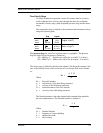
2-1. Minimum Recommended Stud Bolt Lengths ......................... 2-3