


II-49
Audio Setup (Audio)
Chapter 8 Setup ([Setup] Menu)
Audio Setup (Audio)
Assign audio signal inputs to channel faders and make audio related settings in the items of the [Setup] menu > [Audio]
menu.
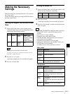
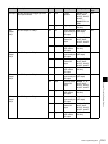
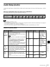
SDI output embedded audio and audio signal combinations
The following table shows the possible combinations for output.
PGM and MIX are handled as a pair.
• When PGM/MIX is assigned to either L or R, the same assignment is made to the other automatically. For example, if
L is assigned to “PGM-L,” R is assigned to “PGM-R.”
• If one of L and R is then assigned to other than PGM/MIX, the other is automatically set to “None.”
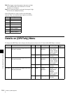
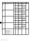
Details on [Audio] Menu
Embedded Audio Possible Combinations for Output
SDI 1 to 4 (L) PGM-L MIX-L AUX1 AUX2 AUX1 AUX2 AUX1 AUX2 None None
SDI 1 to 4 (R) PGM-R MIX-R AUX1 AUX2 AUX2 AUX1 None None AUX1 AUX2
Tip
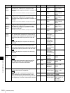
Menu item Description Knob Parameter Meaning Setting range
Audio Input
Assign 1
to
Audio Input
Assign 6
Assign the audio signals input from the audio input
connectors to channel faders 1 to 6.
(c Basic Operation: “Assigning Audio Input Signals
to the Channel Faders”)
Tip
In HD mode, SDI 1 to 4 and HDMI 1 to 3 are handled
in pairs.
• When embedded audio is assigned to either L or
R, the same assignment is made to the other
automatically. For example, if L is assigned to
“SDI1L,” R is assigned to “SDI1R.”
• If one of L and R is then assigned to other than the
embedded audio of, for example, L8, the other is
automatically set to “NotUse.”
V3 Left L audio signal NotUse, M/L1,
M/L2, M/L3, M/L4,
M/L5, M/L6, L7, L8,
SDI1L, SDI2L,
SDI3L, SDI4L,
HDMI1L, HDMI2L,
HDMI3L
V4 Right R audio signal NotUse, M/L1,
M/L2, M/L3, M/L4,
M/L5, M/L6, L7, L8,
SDI1R, SDI2R,
SDI3R, SDI4R,
HDMI1R, HDMI2R,
HDMI3R
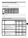
MIC/LINE
1 Level
to
MIC/LINE
6 Level
Adjust the mic/line level for each channel fader.
Adjust a level when, for example, the peak indication
lights red or when the input signal indication does not
light even though an audio signal is being input.
(c Basic Operation: “Assigning Audio Input Signals
to the Channel Faders”)
V4 Level Input level –44 dB, –20 dB,
+4 dB
SDI OUT
PGM
Assign
Assign the audio signals output from PGM OUT/MIX
OUT/AUX OUT 1/AUX OUT 2 connectors to the
embedded audio output from the PGM connector of
SDI OUT.
For details on the possible combinations for output, see page II-49.
V3 Left Audio signal to
assign
None, AUX1,
AUX2, PGM-L,
MIX-L
V4 Right Audio signal to
assign
None, AUX1,
AUX2, PGM-R,
MIX-R