


1-14 (E)
HDS-X5800
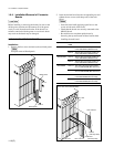
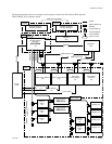
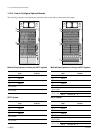
1-9. System Connection
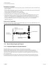
1-9-1. S-BUS Data Link
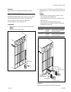
The routing switcher system is connected with the S-BUS data link using a 75 Z coaxial cable.
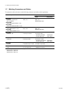
The main equipment of the S-BUS data link is shown in the table below.
Type in S-BUS Model (function name) Quantity Function/rule
data link
Primary station (P)
*
Routing switcher 1 Controls the entire S-BUS data
HDS-X5800 link.
(routing switcher processor) Can also function as a secondary
station.
Secondary station (S)
*
Switcher 253 (max.) Controls the individual secondary
DVS-V6464B/M station.
(video routing switcher) Communicates in accordance with
HDS-X3400/X3600/X3700 the commands from the primary
(multi bit rate routing switcher) station.
DVS-A3232
(audio routing switcher)
DVS-RS1616
(RS-422A remote routing switcher)
DVS-TC3232
(time code routing switcher)
Remote control unit
BKS-R3220
(X-Y control unit)
BKS-R3219
(32 button control unit)
BKS-R1617
(universal control unit)
BKS-R1618
(16 button control unit)
BKS-R3216
(8 destination control unit)
BKS-R3280
(single status display unit)
BKS-R3281
(single status display unit)
Terminal Personal computer 1 Establishes the various setups of
(terminal emulator) the system.
The errors that have occurred in
the S-BUS line are displayed and
managed by the emulator.
*: (P) and (S) indicate the setting of the S/P selector switch on the CPU board in the routing switcher.
n
Switchers other than the HDS-X5800 can be also set as a primary station. In this case, some functions are
limited.
1-9. System Connection