1-22 (E)
HDS-X5800
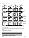
1-10-6. Control System Connection Example and Setup
Input to 1024
*2
232 boards 264 boards 264 boards 264 boards
PFV-SP3300 distributor
HKPF-SP003
HDS-X5800
HDS-X5800
HDS-X5800
PFV-SP3300 distributor
HKPF-SP003
PFV-SP3300 distributor
HKPF-SP003
PFV-SP3300 distributor
HKPF-SP003
Input
exten-
sion
board
HDS-X5800
Input
exten-
sion
board
HDS-X5800
Input
exten-
sion
board
HDS-X5800
Input
exten-
sion
board
HDS-X5800
Input
exten-
sion
board
HDS-X5800
Input
exten-
sion
board
Input 265 to Input 1 to 264
DD
DD
S-BUS
*4
Output
1 to 272
Output
273 to 544
113
4112
2
HDS-X5800
HDS-X5800
HDS-X5800
Input
exten-
sion
board
HDS-X5800
Input
exten-
sion
board
HDS-X5800
Input
exten-
sion
board
HDS-X5800
Input
exten-
sion
board
HDS-X5800
Input
exten-
sion
board
HDS-X5800
Input
exten-
sion
board
DD
DD
S-BUS
*4
REMOTE1 D
*3
REMOTE1 D
*3
REMOTE1 D
*3
REMOTE1 D
*3
75 Z
Output
545 to 816
Output
817 to 1024
*1
114
4112
2
75 Z
75 Z
75 Z
75 Z
S-BUS
*4
1-10. How to Extend Inputs and Outputs
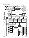
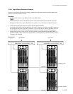
*1 : 1025 up to 1088 cannot be controlled.
*2 : 1025 up to 1056 cannot be controlled.
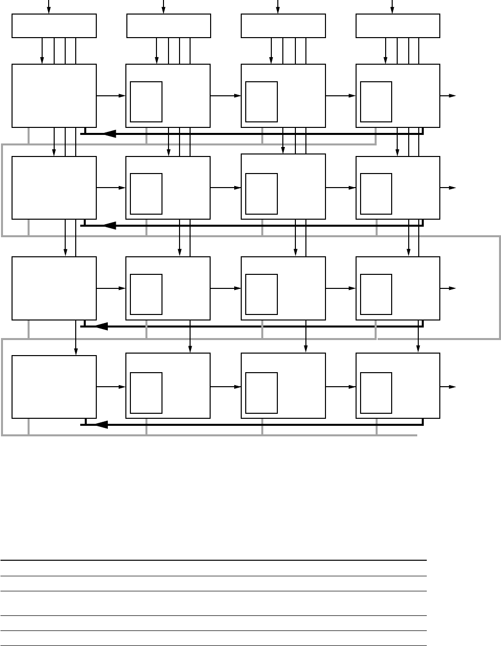
*3 : Connect the REMOTE1 D connector using coaxial cable and terminate the 2 end with 75 Z terminator.
*4 : Connect the REMOTE1 connector using S-BUS cable (coaxial cable) and terminate the final device of the secondary station with 75 Z terminator.
m
.
REMOTE1D provides output in the right and accepts input in the left in the cascade connection as shown in the illustration.
. REMOTE1 A, B, and C have the same function.
. Be sure to terminate the un-used REMOTE1 connectors with 75 Z terminator in both primary and secondary stations.
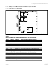
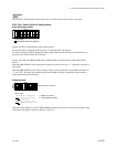
Switch settings of S702/CPU-339 board
1 Bits 1 to 4 to the DOWN position
2 Set the BIT1 through 4 to the DOWN position and set BIT8 to the UP (OPEN) position.
Establish the CASCADE FORMAT setup of the menu item [Z]. (Refer to the System Setup Manual.)
3 Bits 1 to 4 to the UP (OPEN) position
4 Bits 1 to 3 to the DOWN position and bits 4, 8 to the UP (OPEN) position


