


1-35 (E)
HDS-X5800
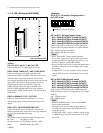
1-11. Setting the On-Board Switches and Description of LEDs
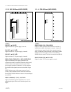
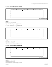
D535, D541, D548, D553 : REFERENCE 625
D535 : REF A
D541 : REF B
D548 : REF C
D553 : REF D
Lights in green when the reference input signal is 625 (PAL).
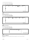
D536, D542, D549, D555 : REFERENCE 1125
D536 : REF A
D542 : REF B
D549 : REF C
D555 : REF D
Lights in green when the reference input signal is 1125 (HD).
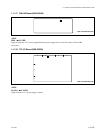
D538, D544, D550, D556 : REFERENCE 750
D538 : REF A
D544 : REF B
D550 : REF C
D556 : REF D
Lights in green when the reference input signal is 750 (HD).
44
44
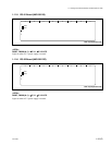
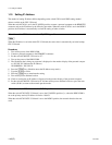
4 FAN STATUS
D514 : FAN (TOP) L1 (rear left on top of the unit)
D516 : FAN (TOP) L2 (front left on top of the unit)
D518 :
FAN (TOP) C1 (
rear
center on top of the unit)
D520 : F
AN (TOP) C2 (front center on top of the unit)
D522 : FAN (TOP) R1
(
rear
right on top of the
unit
)
D525 : FAN
(TOP) R2 (front right on top of the unit)
D528 : FAN (BOTTOM) L1 (rear left in the bottom
of the unit)
D531 : FAN (BOTTOM) L2 (front left in the bottom
of the unit)
D534 : FAN (BOTTOM) C1 (rear center in the
bottom of the unit)
D537 : FAN (BOTTOM) C2 (front center in the
bottom of the unit)
D540 : FAN (BOTTOM) R1 (rear right in the
bottom of the unit)
D543 : FAN (BOTTOM) R2 (front right in the
bottom of the unit)
D545 : FAN (REAR) 1 (rear left of the unit)
D547 : FAN (REAR) 2 (rear right of the unit)
Fan status indication. It Lights in green when the fan is
working normally. It Lights in red when the fan has an error.
55
55
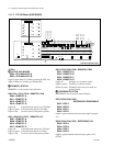
5 SIGNAL STATUS
D1 to D272 : DETECT INPUT/OUTPUT/IN ERR/OUT ERR
When the LED is set in the mode in which presence/absence
of the input/output signal is displayed, its presence or
absence is displayed. When the LED is set in the mode in
which location of error of the input/output signal is
displayed, its presence or absence of error is displayed. The
indication mode of the LED is switched by the switch S105.
Lights in green : Signal is present.
Flashes in green : Error occurs.
Lights off : No signal/No error
(Different depending on the display
mode)
66
66
6 Mode selection of signal status (D1 to D272)
D507 : INPUT
In the mode in which presence/absence of input signal is
indicated, it flashes in green.
D509 : OUTPUT
In the mode in which presence/absence of output signal is
indicated, it flashes in green.
D510 : IN ERR
In the mode in which error of input signal is indicated, it
flashes in green.
D512 : OUT ERR
In the mode in which error of output signal is indicated, it
flashes in green.
77
77
7 COMMUNICATION STATUS
D1002 : COM RUN
Operating status of the CPU on the FP-129 board is indicated.
Lights in green : CPU is running.
Lights off : CPU operation is faulty.
D1003 : COM ERR
Operating status of the CPU on the FP-129 board is indicated.
Lights in red : An error occurs in CPU.
Lights off : CPU operation is faulty.
D1004 : COM TX
Operating status of the CPU on the FP-129 board is indicated.
Lights in green when sending data to the main CPU.
D1005 : COM RX
Operating status of the CPU on the FP-129 board is indicated.
Lights in green when receiving data from the main CPU.