


2-9 (E)
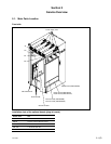
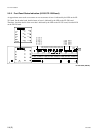
HDS-X5800
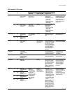
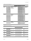
Name of LED
FAN L1
(TOP)
L2
C1
C2
R1
R2
FAN L1
(BOTTOM)
L2
C1
C2
R1
R2
FAN 1
(REAR)
2
Ref No.
D514
D516
D518
D520
D522
D525
D528
D531
D534
D537
D540
D543
D545
D547
Contents
Status of the fan
in the HDS-
X5800 (Top of
the HDS-X5800)
Status of the fan
in the HDS-
X5800 (Bottom
of the HDS-
X5800)
Status of the fan
in the HDS-
X5800 (Rear of
the HDS-X5800)
Status
Lights in green
Normal
Normal
Normal
Lights in red
Fan in the rear left on top of the
HDS-X5800 is abnormal.
Fan in the front left on top of the
HDS-X5800 is abnormal.
Fan in the rear center on top of the
HDS-X5800 is abnormal.
Fan in the front center on top of the
HDS-X5800 is abnormal.
Fan in the rear right on top of the
HDS-X5800 is abnormal.
Fan in the front right on top of the
HDS-X5800 is abnormal.
Fan in the rear left on the bottom of
the HDS-X5800 is abnormal.
Fan in the front left on the bottom of
the HDS-X5800 is abnormal.
Fan in the
rear
center on the bottom
of the HDS-X5800 is abnormal.
Fan in the front center on the bottom
of the HDS-X5800 is abnormal.
Fan in the rear right on the bottom of
the HDS-X5800 is abnormal.
Fan in the front right on the bottom
of the HDS-X5800 is abnormal.
Fan in the left (when viewed from
the front) on rear of the HDS-X5800
is abnormal.
Fan in the right (when viewed from
the front) on rear of the HDS-X5800
is abnormal.
Remedy
Replace the
defective fan.
Replace the
defective fan.
Replace the
defective fan.
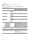
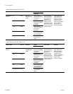
. When D5 on the LE-251 lights in red
Error status
Lights in red
The system A has fault when REMOTE1 A
is primary station (D521 lights in green).
(75-ohm terminator is disconnected.)
The system B has fault when REMOTE1 B
is primary station (D523 lights in green).
(75-ohm terminator is disconnected.)
The system C has fault when REMOTE1 C
is primary station (D524 lights in green).
(75-ohm terminator is disconnected.)
The system D has fault when REMOTE1 D
is primary station (D526 lights in green).
(75-ohm terminator is disconnected.)
Name of LED
REMOTE1 312
(REM1A)
1250
REMOTE1 312
(REM1B)
1250
REMOTE1 312
(REM1C)
1250
REMOTE1 312
(REM1D)
1250
Ref. No.
D501
D504
D508
D511
D513
D515
D517
D519
Contents
Status of the
REMOTE1 system A
Status of the
REMOTE1 system B
Status of the
REMOTE1 system C
Status of the
REMOTE1 system D
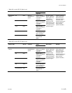
. When D8 on the LE-251 lights in red
Remedy
Check connection of the
equipment.
Install the 75-ohm terminator.
Check connection of the
equipment.
Install the 75-ohm terminator.
Check connection of the
equipment.
Install the 75-ohm terminator.
Check connection of the
equipment.
Install the 75-ohm terminator.
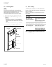
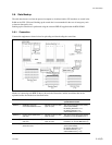
2-3. Error Indication