


1-15 (E)
HDS-X5800
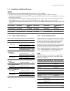
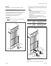
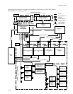
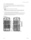
The following diagram shows an example of the connection for the data link of the S-BUS when the
HDS-X5800 is set as a primary station.
: S-BUS
: Signal system line
: Ethernet
: T-type bridge (A)
: T-type bridge (B)
: 75 Z terminator
: Layer of matrix
Terminal
Primary
station
Secondary
station
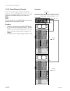
Level 1
Personal computer
(terminal emulator)
Personal computer
(terminal emulator)
Routing switcher
processor
HDS-X5800
(
P
)
Source
VTR
Destination
VTR
Video
Time code
Audio channel 1/2
Audio channel 3/4
Audio channel
1/2
Audio channel
3/4
Audio routing switcher
(
S
)
Audio routing switcher
(
S
)
Time code
routing switcher
(
S
)
Each routing
switchers
(S)
Maximum 4 equipment
Level 8Level 4Level 3Level 2
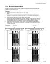
Video
REMOTE1 A
REMOTE1 B1
REMOTE1 B2
REMOTE1 C
REMOTE1 D
Ethernet
Hub
Terminal
DATA
Time code
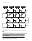
Tertiary station
Maximum 128
equipment
Remote
control
unit
Remote
control
unit
Remote
control
unit
Subnet controller
BZR-IF310
Subnet controller
BZR-IF310
Remote
control
unit
Remote
control
unit
Display unit
Display unit
Display unit
Display unit
1-9. System Connection