


1-26 (E)
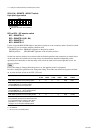
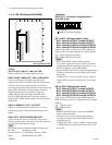
HDS-X5800
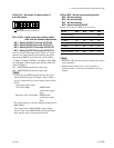
OPEN
12345678
Factory setting
( indicates the switch lever position.)
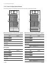
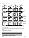
S702 (E-8) : REMOTE 1 SELECT switch
8-pin piano-type switch
BIT1 to BIT4 : S/P selector switch
BIT1 : REMOTE1 A
BIT2 : REMOTE1 B (B1, B2)
BIT3 : REMOTE1 C
BIT4 : REMOTE1 D
Used to assign the HDS-X5800 either to the primary station or to the secondary station. Set the bit switch
from bits 1 to 4 in accordance with the connector used.
UP (OPEN) position : PRIMARY (Operates as the primary station)
DOWN position : SECONDARY (Operates as the secondary station)
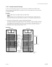
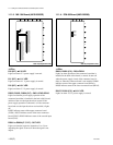
Set the four selector switches in accordance with the desired operations and connections as shown below.
At the same time, the switches whose setup values are automatically determined depending on the
operations and connections so that the setup values cannot be made valid even though they are set, are
shown as follows.
n
Even if the setting is changed while the power is on, the operation mode is not updated.
In order to change the operation mode, change the setting. Then either turn off the main power and back
on, or press the reset switch on the CPU-339 board.
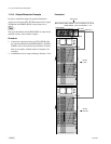
Operation and connection S702-1 S702-2 S702-3 S702-4 S702-8 S703-5
A-S/P B-S/P C-S/P D-S/P CAS 128/32
HDS-X5800 operates as the primary station PPPPValid Valid
HDS-X5800 operates as the primary station PPSPInvalid
*
Valid
and the REMOTE1 C is used to extend
the MVS-8000 series at the same time
HDS-X5800 operates as the primary station PPSSInvalid
*
Valid
and the REMOTE1 C, 1 D are used to extend
the MVS-8000 series at the same time
HDS-X5800 operates as the secondary station S S
_
S Valid Invalid
HDS-X5800 is used as the secondary station S S
_
P Valid Invalid
in the cascade connection and at the same time
it is connected where it outputs a video signal
(equivalent to 3 and 4on Section 1-10-6
on page 1-24) in the entire cascade system
P : PRIMARY
S : SECONDARY
* : Be sure to set to the DOWN position.
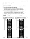
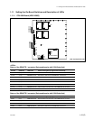
1-11. Setting the On-Board Switches and Description of LEDs