54
Installation and Adjustment
Connections (continued)
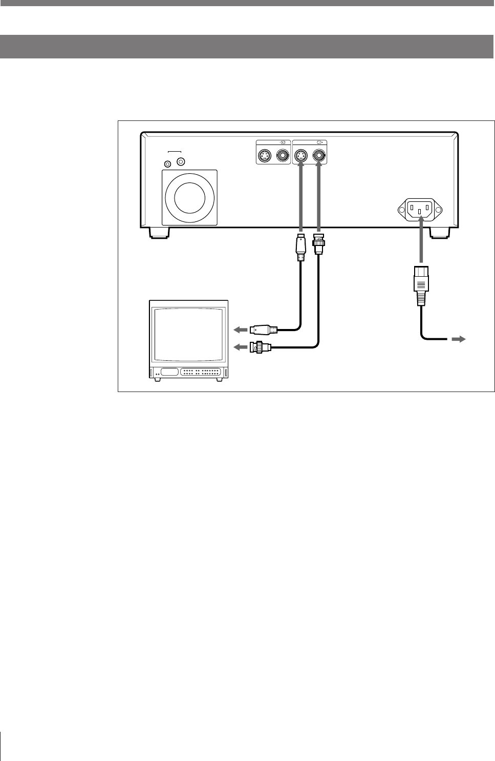
Making Connections for Viewing Images to be Printed
Connect a video monitor to view stored images and to check those to be printed.
Connect the necessary video monitor which will be used in actual printing, using
the following diagram as a guide.
Video monitor
UP-2100/2100SD
Connecting cable (with
DIN 4-pin connectors)
YC-15EV
to S-VIDEO
input connector
to composite video
input connector
75-ohm coaxial
cable with BNC
connectors
to S-VIDEO OUTPUT
to VIDEO OUTPUT
to wall outlet
AC power cord
(supplied)
to AC IN
p When the video monitor color does not match to that of a printout
It is difficult to image printout results because the video monitor color does not
match to that of a printout. In such a case, the video monitor color may not be
adjusted correctly even if the printer color is correctly adjusted. Check the color
adjustment of the video monitor.
The printer outputs either of the following two kinds of video signals according to
the printer setting described below.
• EE (E to E): Signals are output to the monitor after being processed by the
printer‘s circuitry.
• THRU (THROUGH): Signals are output to the printer as is.
Use the THROUGH signal to check the video monitor.
When you select THRU, the signal flow inside the printer is as follows.
— Signal input to the VIDEO IN connector n Outputs to the VIDEO OUT
connector.
— Signal input to the S VIDEO IN connector n Outputs to the S VIDEO OUT
connector.
To set the printer output to THRU
1 Press the MENU button, then display the OUTPUT SETUP menu by pressing
the ı or ∫ button.
2 Select SOURCE by pressing the ◊ or √ button.
3 Select THRU by pressing the ı or ∫ button.
For details of how to make adjustments using menus, see “Setting Up the Printer” on page 56.
INPUT
S-VIDEO VIDEO
~
AC IN
12
REMOTE
OUTPUT
S-VIDEO VIDEO


