42 Sun StorageTek 2500 Series Array Hardware Installation Guide • March 2007
Connecting the Power Cables
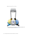
1. Verify that both power switches are turned off.
2. Verify that the circuit breakers in the cabinet are turned off.
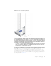
3. Connect each power supply in the tray to a separate power source in the
cabinet.
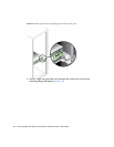
4. Connect the primary power cables from the cabinet to the external power
source.
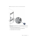
Note – Do not power on the array until you complete the procedures in this chapter.
The power-on sequence is described in detail in Chapter 4.
Intertray Cabling
This section describes how to cable a controller tray to expansion trays for several
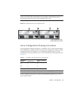
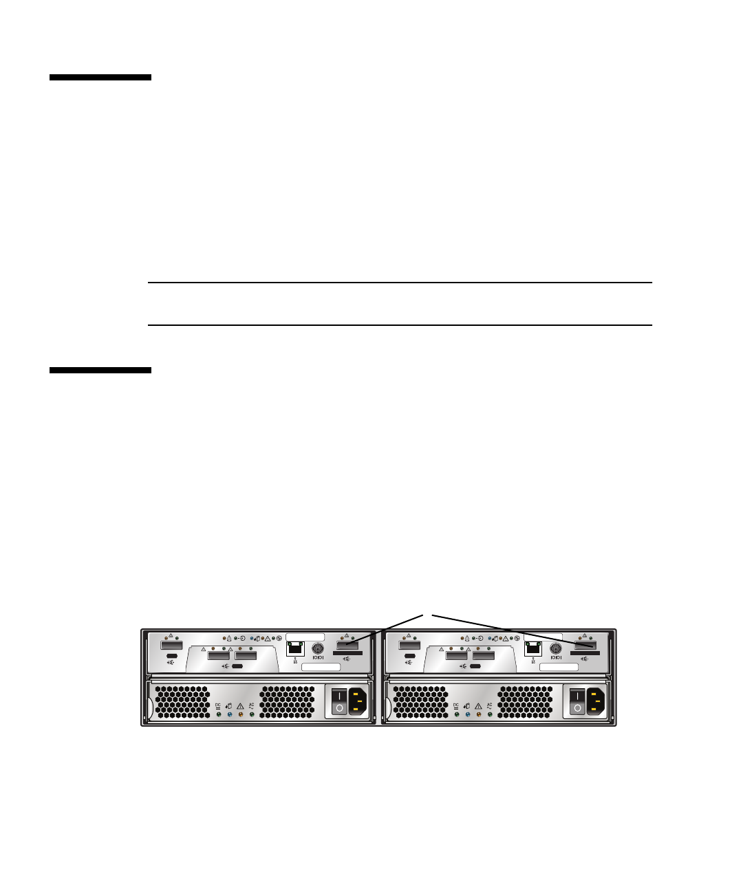
different configurations. Each controller has one expansion port (
FIGURE 2-16).
Controller A controls drive channel 1 through the A-side drive modules; Controller
B controls drive channel 2 through the B-side modules. Each drive channel provides
a separate path for data transfer from the controller tray to the expansion trays; the
two channels provide redundancy.
FIGURE 2-16 Expansion Ports on the Controller Tray
Each expansion tray has two SAS port connectors, one marked with an up arrow
and the other marked with a down arrow (
FIGURE 2-17). You use SAS cables to
connect expansion trays to controllers.
Link Link
HOST
1
S
A
S
LinkLink LinkLink
HOST
23
S
A
S
Link Link
DRIVE EXPANSION
S
A
S
Link Link
HOST
1
S
A
S
LinkLink LinkLink
HOST
23
S
A
S
Link Link
DRIVE EXPANSION
S
A
S
SAS Expansion Ports to the Expansion Tray


