


Operational Theory 2Operational Theory 2
Operational Theory 2Operational Theory 2
Operational Theory 2
2-7
TELEDYNE ANALYTICAL INSTRUMENTS
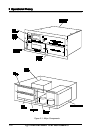
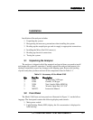
The analog output printed circuit board (PCB) generates the two 0–1 volt and the
two 4–20 mA analog signal outputs available on the rear panel of the analyzer. These
signals, generated in digital format by the microcomputer, are converted into analog
signals by the circuitry on this PCB. The output signals represent the following:
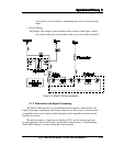
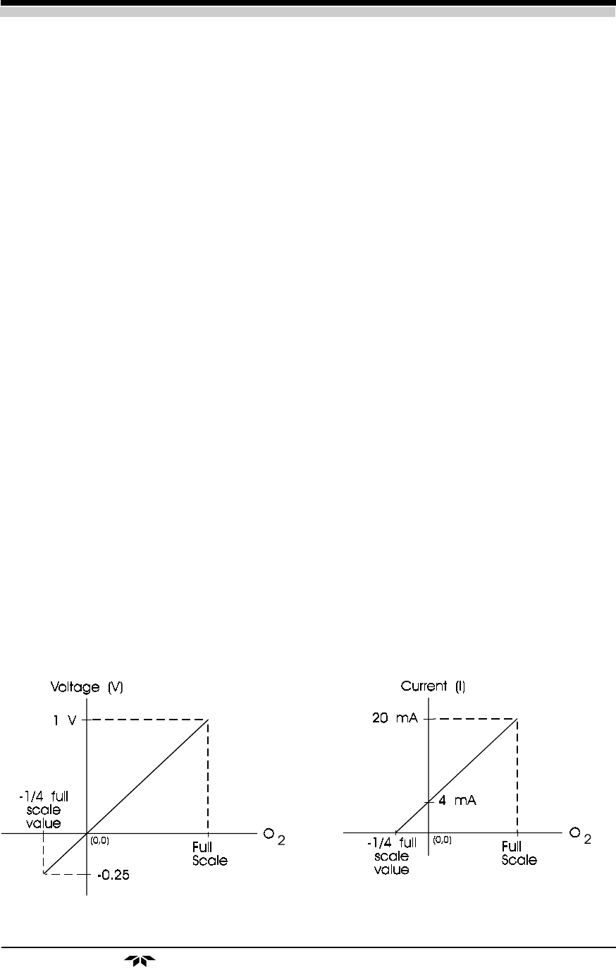
• 0–1V Signal (Oxygen Measurement): This output goes from 0 to 1, represent-
ing 0 to 100% of the scale that has been set; i.e., 0.6 volt is equal to 60% of the full
scale, or 6 PPM when on the 10 PPM scale. It is possible that the signal may go past
zero into the negative range up to -0.25, especially if the analyzer has been zeroed
with a gas that contains a significant concentration of oxygen. See Figure 2-3.
• 0-1V Range Identifier: This 0 to 1 volt output represents each range with a
particular voltage as shown in Table 2–1.
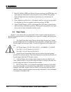
• Isolated 4–20 mA Signal (Oxygen Measurement): This is a 4 to 20 mA output
representing 0 to 100% of the scale, with 4 mA equal to 0%, and 20 mA equal to
100% of that range. This output may also range lower than 4 mA, especially if the
analyzer has been zeroed with a gas that contains a significant concentration of oxy-
gen. See Figure 2-3.
• Isolated 4–20 mA Range Identifier: This 4 to 20 mA output represents
individual ranges with discrete current output as shown in Table 2-1.
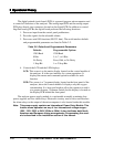
Table 2-1. Range Identifier
Identifier Identifier
Range Scale Voltage (V) Current(mA)
1 1 PPM 0.0 4.0
2 10 PPM 0.2 7.2
3 100 PPM 0.4 10.4
4 1000 PPM 0.6 13.6
5 1% 0.8 16.8
6 25% 1.0 20.0
Figure 2-3: Analog signal output offset