


3-8
3 Installation3 Installation
3 Installation3 Installation
3 Installation
TELEDYNE ANALYTICAL INSTRUMENTS
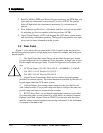
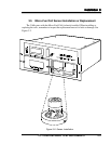
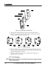
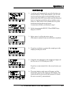
Figure 3-4: Removing the Voltage Card
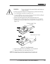
4. Turn the card so that the desired voltage can be read at the bottom.
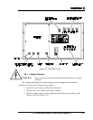
5. Slide the indicator pin around the card so that it is pointing up when the
voltage is read at the bottom (see Figure 3–5).
Figure 3–5: Voltage Selection
6. Place the voltage selector card back into the housing. The edge where the
desired voltage is printed should go in first and the printed side of the card
should be facing the IEC connector.
7. Replace the fuse block and the cover. Verify that the indicator pin is
pointing to the correct voltage.
3.6.2 Fuse Changing
NOTE:Spare fuses are located in a clip attached to the power supply enclosure
inside of the analyzer.