


3-2
3 Installation3 Installation
3 Installation3 Installation
3 Installation
TELEDYNE ANALYTICAL INSTRUMENTS
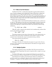
3. Parts Per Million (PPM) and Percent Oxygen indicators: the PPM light will
light while the instrument is measuring O
2
in units of PPM. The percent
light will light while the instrument is measuring O
2
concentration in
percent.
4. Flow Indicator and Flow Set: a flowmeter and flow set knob are provided
for adjusting gas flow in standard cubic feet per hour (SCFH).
5. Liquid Crystal Display (LCD) with keypad: the LCD shows system menus
and data during instrument operation. The keypad is the primary user-input
device used to enter information in the system.
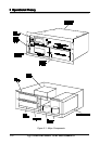
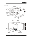
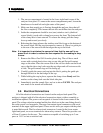
3.3 Rear Panel
Figure 3–1 also shows the rear panel of the 3160. Located on the rear panel are
the following electrical power and gas input ports, alarm relay outputs, and analog and
digital outputs:
1. Gas Input/Vent: three input fittings are provided for span gas, sample
gas, and compressed air for pneumatic valve operation. A single vent is used
for the sample and span gas outlet. Consult the Appendix for scrubber selec-
tion.
2. AC Power Input: 110, 120, 220 or 240 V ~ at 50/60 Hz 1.5 A MAX.
Use 250 V 1.6 A T Fuse for 110, 120 V ~
Use 250 V 0.8 A T Fuse for 220, 240 V ~
3. Alarm Circuit Connections: there are five contact closures/openings
provided for external alarms. The alarm functions are defined by the user via
keypad input within the LCD menu system.
4. Analog Outputs: four analog output connectors are provided for use
with a chart recorder. Two provide range and data in voltages; the other two
provide range and data for current-driven recorders.
5. RS-232 Serial Port: a 9–pin digital input/output connector is provided
for connecting either a serial printer or a serial link to an external computer.
Optional serial link software (such as TRACS) can be used with the instru-
ment for remote external computer monitoring and control of the instrument,
via modem or hardware link.