


Operations 4Operations 4
Operations 4Operations 4
Operations 4
4-1
TELEDYNE ANALYTICAL INSTRUMENTS
Operations
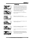
4.1 Front Panel Controls
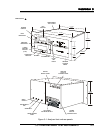
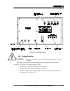
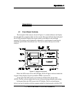
The front panel of the analyzer, shown in Figure 4-1, contains indicators and displays
through which the computer module can be accessed. The upper left-hand side of the panel
has an LED screen that displays the oxygen content of the sample in one-inch high
numerals. This display can be brightened or dimmed by a potentiometer located directly
behind the panel inside of the analyzer case. To access it, remove the top cover of the
analyzer.
Figure 4.1: Analyzer front panel.
Below the LED screen are two red LED lights. Each will light to indicate whether the
oxygen is being displayed in parts per million (PPM) or percent (%).
To the right of the LED screen is a flowmeter in standard cubic feet per hour
(SCFH). The flow set knob adjusts the flow rate of the gas during calibration and zeroing.
In the panel below the LED screen is the LCD display. The five colored buttons
below it are used to interface with the computer module in selecting modes, with the LCD