


5-3
Maintenance & Maintenance &
Maintenance & Maintenance &
Maintenance &
TT
TT
T
rr
rr
r
ouboub
ouboub
oub
leshooting 5leshooting 5
leshooting 5leshooting 5
leshooting 5
TELEDYNE ANALYTICAL INSTRUMENTS
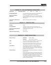
SymptomSymptom
SymptomSymptom
Symptom
CauseCause
CauseCause
Cause
CorrectionCorrection
CorrectionCorrection
Correction
Will not switch modes.Will not switch modes.
Will not switch modes.Will not switch modes.
Will not switch modes.
Sensor output does not dropSensor output does not drop
Sensor output does not dropSensor output does not drop
Sensor output does not drop
to a stable, low value duringto a stable, low value during
to a stable, low value duringto a stable, low value during
to a stable, low value during
zeroing or spanning.zeroing or spanning.
zeroing or spanning.zeroing or spanning.
zeroing or spanning.
Unit will not turn on althoughUnit will not turn on although
Unit will not turn on althoughUnit will not turn on although
Unit will not turn on although
it is plugged in and theit is plugged in and the
it is plugged in and theit is plugged in and the
it is plugged in and the
Power Switch is ON (at "I"Power Switch is ON (at "I"
Power Switch is ON (at "I"Power Switch is ON (at "I"
Power Switch is ON (at "I"
position).position).
position).position).
position).
Back panel vent is blocked.
See a) above.
a) Sensor has been exposed
to high concentrations of O
2
for an extended time period.
b) Bad sensor.
c) Leak in system.
Fuse is blown.
c) Make sure metering valve
(flow set knob on front
panel) is sufficiently open.
Clear and check connection to
back panel vent.
See a) above.
a) Replace sensor
and/orand/or
and/orand/or
and/or
wait for stable reading.
b) Replace sensor.
c) Check sensor block clamp.
Make sure the sensor block
is tightly closed. Check the
gas supply tank, line and
connections for leaks.
Check fuse(s) in back panel
fuse block assembly located
above the power cord recep-
tacle.