


5-2
5 Maintenance & 5 Maintenance &
5 Maintenance & 5 Maintenance &
5 Maintenance &
TT
TT
T
rr
rr
r
ouboub
ouboub
oub
leshootingleshooting
leshootingleshooting
leshooting
TELEDYNE ANALYTICAL INSTRUMENTS
Analyzers equipped with a scrubber should only be used with inert gases and saturat-
ed hydrocarbons.
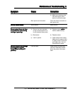
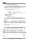
5.2 Troubleshooting
To troubleshoot the analyzer, identify the problem in the following list and then
follow the procedures to correct the problem. If you cannot identify the problem, or if you
cannot resolve the problem after following the corrective procedure, call a service repre-
sentative.
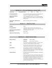
LCD or LED display will notLCD or LED display will not
LCD or LED display will notLCD or LED display will not
LCD or LED display will not
light.light.
light.light.
light.
Display too bright.Display too bright.
Display too bright.Display too bright.
Display too bright.
No analog output.No analog output.
No analog output.No analog output.
No analog output.
Zero gas signal >2 PPM.Zero gas signal >2 PPM.
Zero gas signal >2 PPM.Zero gas signal >2 PPM.
Zero gas signal >2 PPM.
Slow response/recovery time.Slow response/recovery time.
Slow response/recovery time.Slow response/recovery time.
Slow response/recovery time.
Displays “--” value.Displays “--” value.
Displays “--” value.Displays “--” value.
Displays “--” value.
Can't calibrate (with sensorCan't calibrate (with sensor
Can't calibrate (with sensorCan't calibrate (with sensor
Can't calibrate (with sensor
installed). Display reads “cellinstalled). Display reads “cell
installed). Display reads “cellinstalled). Display reads “cell
installed). Display reads “cell
too strong” or “cell tootoo strong” or “cell too
too strong” or “cell tootoo strong” or “cell too
too strong” or “cell too
weak.”weak.”
weak.”weak.”
weak.”
No sample gas flow.No sample gas flow.
No sample gas flow.No sample gas flow.
No sample gas flow.
Return the unit to factory.
Remove analyzer cover. Adjust
potentiometer located behind
LCD display.
Remove analyzer cover. Check
PC board connections and
make sure that they are firmly
seated.
Replace sensor.
Check zero gas inlet connec-
tion.
Replace sensor.
Re-zero sensor.
a) Re-enter span gas concen-
tration.
b) Replace or reinstall sensor.
a) Raise air supply pressure to
at least 70 psig.
b) Check back panel connec-
tions. Raise sample supply
to at least 5 psig but within
±2 psig of the span gas
pressure.
Faulty LCD or LED.
Faulty electrical connection.
Bad sensor.
High O
2
level.
Bad sensor.
a) The wrong span gas
concentration has been
entered.
a) The pneumatic air supply
pressure is too low, making
the valves stick.
b) The sample supply pressure
is too low.
SymptomSymptom
SymptomSymptom
Symptom
CauseCause
CauseCause
Cause
CorrectionCorrection
CorrectionCorrection
Correction