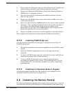
1. Ensure that the notebook is powered off and that the AC Adapter and
internal battery pack(s) is (are) removed from the notebook.
2. Remove the Expansion RAM Module (Dual Inline Memory Module or
DIMM) from its shipping container.
3. Turn the Notebook over and locate the RAM Access Door (held in
place by two screws).
4
. Remove the two Phillips-head screws that hold the RAM access door
and remove the door.
5. Insert the edge of the first DIMM Board into the rear of either available
connector . Use a rocking motion and insert the board at an angle to
the surface of the Main Board. Fully insert the module. Push
downwards on each side of the DIMM module until it snaps in place.
Repeat the procedure for the second module.
6. Replace the RAM Access Door and all components removed in Step 1.
This completes the expansion memory module installation procedure.
2.3.2
Installing PCMCIA Options
The Notebook has provisions for two Type I or II options or one Type III
PCMCIA option card.
1. Review the installation instructions supplied with the PCMCIA option
card(s).
2. Open the PCMCIA compartment cover on the right side of the
notebook.
3. To insert a PCMCIA card, align the card with the socket and slide the
card into the socket until it locks into place.
4. To eject a PCMCIA card, first ensure that the notebook is not
accessing the memory card or device. Under Windows 95, go to the
Control Panel, PC Card selection and direct the card to stop before
removing card.
2.3.3
Installing the Optional Numeric Keypad
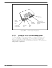
An optional numeric keyboard can be attached to the notebook via the
notebook’s PS/2 connector (refer to Figure 2-2).
2.4
Installing the Battery Pack(s)
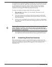
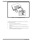
The Extensa Notebook is shipped with a single battery pack that is inserted
from the front left side of the computer. A second battery pack (option) can
2-2
Installation


