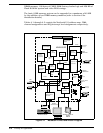
DRAM memory, 128 bytes of CMOS RAM (battery backed up) and 256 KB of
Flash ROM for system and video BIOS storage.
The basic 8 MB memory system can be expanded to a maximum of 40 MB
by the addition of two DIMM memory modules (refer to Section 6 for
installation details).
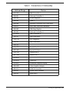
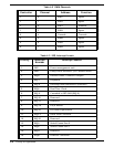
Tables 4-1 through 4-3 contain the Notebook I/O address map, DMA
channel assignments and IRQ interrupt level assignments respectively.
MAIN BOARD
SYSTEM &
SVGA BIOS
INTERNAL 1.44 MB
FLOPPY DISK DRIVE
PARALLEL
PRINTER PORT
Super I/O
Controller
RS232
SERIAL PORT
Drivers/
Receivers
Expansion Bus
Connector
PCMCIA Adapter
UM8365A
SIR
Interface
PCMCIA Option Slot(s)
Pentium
Processor
(P54C/LM)
IR/Sound
Board
DRAM
(2 Bank)
PCI Bus
Cache MEMORY
DBC
82C556
Audio IN/OUT
Mic In
CPU Data
System
Controller
82C557
CPU Address
IPC
Memory
Data
EXTERNAL
SVGA MONITOR
Input From
AC Adapter
Battery Packs
Video
Controller
INTERNAL KEYBOARD
1 MB
Video RAM
640 X 480
SVGA LCD
INTERNAL LCD DISPLAY
Internal
Glidepad
PMU/Keyboard
Controller
HDD
CD-ROM
SIMM Memory
Expansion
Modules
RTC
82C602A
PCI Bus
PCI Bus
IR/Audio
Board
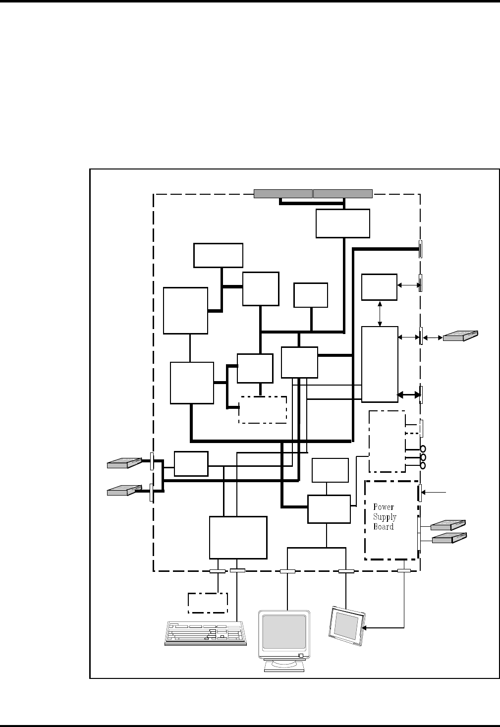
Figure 4-1 Notebook Functional Block Diagram
4-2
Theory of Operation


