


Fehler! Formatvorlage nicht definiert. Fehler! Formatvorlage nicht definiert. Fehler!
Formatvorlage nicht definiert. Fehler! Formatvorlage nicht definiert.
Rev D
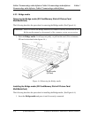
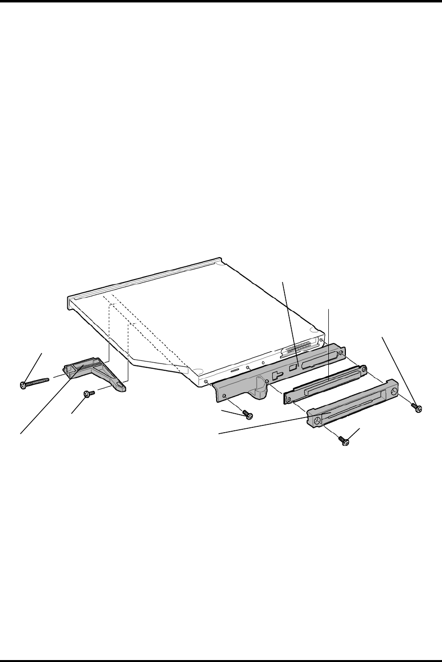
PORTÉGÉ M700 only
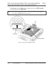
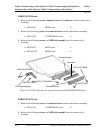
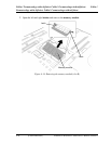
4. Remove the following screws, connector cover and connector from the optical drive
assembly.
• M2.0×6.0C BIND screw ×2
5. Remove the following screw and connector base from the optical drive assembly.
• M2.0×3.0C S-THIN HEAD screw ×1
6. Remove the following screws and ODD side assembly from the optical drive
assembly
• M2.0×6.0C BIND screw ×1
• M2.0×22.0C BIND screw ×1
Connector base
Connecto
r
4-22 [CONFIDENTIAL] PORTÉGÉ M700/M750 Maintenance Manual (960-661)
Figure 4-11-PATA Detaching the optical drive assembly(PORTÉGÉ M700 only)
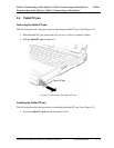
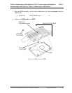
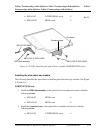
PORTÉGÉ M750 only
4. Remove the following screw and connector base from the optical drive assembly.
• M2.0×3.0C S-THIN HEAD screw ×2
6. Remove the following screws and ODD side assembly from the optical drive
assembly
M2.0×6.0C BIND
M2.0×6.0C BIND
M2.0×3.0C S-THIN HEAD
M2.0×6.0C BIND
M2.0×22.0C BIND
ODD side assembly
Connector cover