


Fehler! Formatvorlage nicht definiert. Fehler! Formatvorlage nicht definiert. Fehler!
Formatvorlage nicht definiert. Fehler! Formatvorlage nicht definiert.
4-46 [CONFIDENTIAL] PORTÉGÉ M700/M750 Maintenance Manual (960-661)
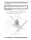
Installing the base assembly and cover assembly
The following describes the procedure for installing the base assembly and cover assembly.
(See Figure 4-24 and 4-26.)
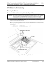
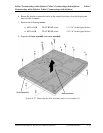
1. Place the base assembly onto the cover assembly and secure them with the
following screws.
• M2.5×16.0B FLAT HEAD screw ×3 (“16” in the figure 4-26)
• M2.5×6.0B FLAT HEAD screw ×10 (“6” in the figure 4-26)
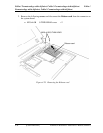
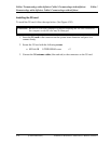
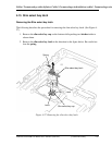
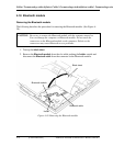
2. Turn the computer face up and stand the display 90 degrees.
3. Turn the display clockwise 90 degrees.
4. Secure the following screws.
• M2.5×10.0B FLAT HEAD screw ×2
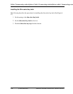
5. Turn the display counter clockwise 90 degrees. (The display is returned to the former
position.)
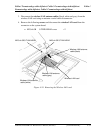
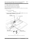
6. Set the hinge rear cover.
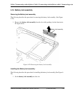
7. Connect the touch pad cable, LCD cable and digitizer cable to the connector
CN3240, CN5601, and CN9540 on the system board.
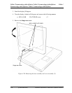
8. Secure the base assembly and cover assembly with the following screw.
• M2.0×4.0B BIND screw ×1