Fehler! Formatvorlage nicht definiert. Fehler! Formatvorlage nicht definiert.
F
ehler! Formatvorla
g
e nic
h
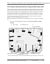
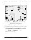
LCD cover assembly
Hinge assembly
M2.5x6.0B FLAT HEAD
M2.5x6.0B FLAT HEAD
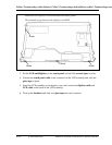
Figure 4-59a Removing the wireless LAN antenna/3G antenna/Internal
microphone/webcamera cable(3G model only)
Installing the Wireless LAN antenna/Internal microphone/Web camera cable
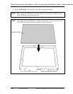
The following describes the procedure for installing the LCD cover assembly. (See Figure 4-
57.)
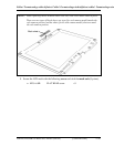
1. Set the hinge assembly onto the LCD cover assembly and secure them with the
following screws.
• M2.5×6.0B FLAT HEAD screw ×2
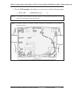
2. Set the antennas and cables in place.
4-110 [CONFIDENTIAL] PORTÉGÉ M700/M750 Maintenance Manual (960-661)


