


Fehler! Formatvorlage nicht definiert. Fehler! Formatvorlage nicht definiert. Fehler!
Formatvorlage nicht definiert. Fehler! Formatvorlage nicht definiert.
4-24 [CONFIDENTIAL] PORTÉGÉ M700/M750 Maintenance Manual (960-661)
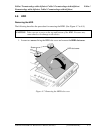
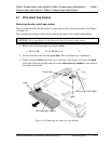
3. Install the connector cover and connector to the optical drive assembly and secure
them with the following screws.
• M2.0×6.0C BIND screw ×2
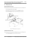
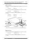
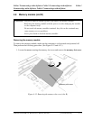
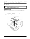
4. Insert the slim select bay module into the slot to connect it to the connector on the
system board. Press to ensure a firm connection.
5. Remove the following screw from the screw hole. Then secure the latch with the
removed screw. (The slim select bay is locked.)
• M2.5×4.0B FLAT HEAD screw ×1
PORTÉGÉ M750 only
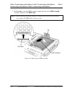
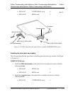
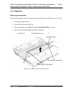
1. Install the ODD side assembly to the optical drive assembly and secure it with the
following screws.
• M2.0×3.0C S-THIN HEAD screw ×1
• M2.0×22.0C BIND screw ×1
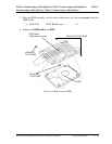
2. Install the connector base to the optical drive assembly and secure it with the
following screw.
• M2.0×3.0C S-THIN HEAD screw ×2
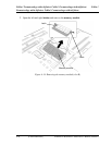
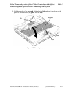
3. Insert the slim select bay module into the slot to connect it to the connector on the
system board. Press to ensure a firm connection.
4. Remove the following screw from the screw hole. Then secure the latch with the
removed screw. (The slim select bay is locked.)
• M2.5×4.0B FLAT HEAD screw ×1