


Fehler! Formatvorlage nicht definiert. Fehler! Formatvorlage nicht definiert. Fehler!
Formatvorlage nicht definiert. Fehler! Formatvorlage nicht definiert.
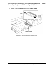
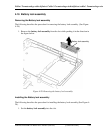
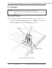
4.14 Base assembly and Cover assembly
Removing the base assembly and cover assembly
The following describes the procedure for removing the base assembly and cover assembly.
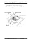
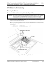
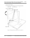
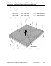
(See Figure 4-24 to 4-26.)
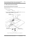
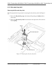
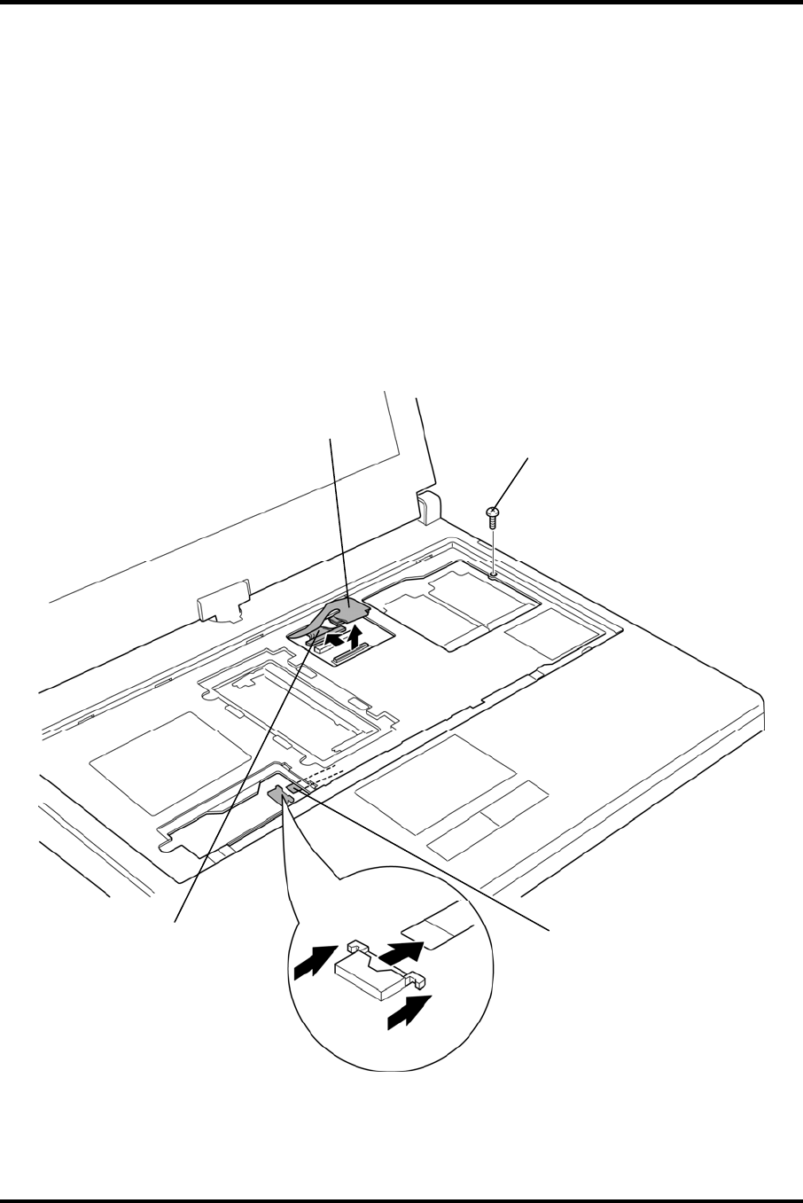
1. Remove the following screw.
• M2.0×4.0B BIND screw ×1
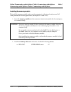
2. Disconnect the touch pad cable, LCD cable and digitizer cable from the connector
CN3240, CN5601, and CN9540 on the system board.
M2.0×4.0B BIND
Touch pad cable
(connected to CN32
LCD cable
(connected to CN5601)
40)
Digitizer cable
(connected to CN9540)
Figure 4-25 Removing the base assembly and cover assembly (1)
PORTÉGÉ M700/M750 Maintenance Manual (960-661) [CONFIDENTIAL] 4-43