


© 2005 - 2009 TOSHIBA TEC CORPORATION All rights reserved MR-2017/2020
CONTENTS
1
CONTENTS
MR-2017/2020
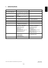
1. SPECIFICATION ........................................................................................................... 1-1
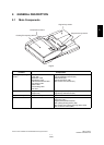
2. GENERAL DESCRIPTION............................................................................................ 2-1
2.1 Main Components................................................................................................................ 2-1
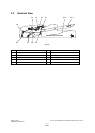
2.2 Sectional View ..................................................................................................................... 2-2
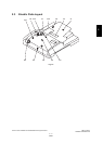
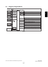
2.3 Electric Parts Layout............................................................................................................ 2-3
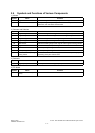
2.4 Symbols and Functions of Various Components................................................................. 2-4
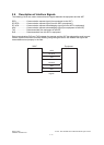
2.5 Diagram of Signal Blocks.....................................................................................................2-5
2.6 Description of Interface Signals ........................................................................................... 2-6
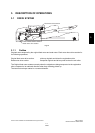
3. DESCRIPTION OF OPERATIONS ............................................................................... 3-1
3.1 DRIVE SYSTEM .................................................................................................................. 3-1
3.1.1 Outline ...................................................................................................................... 3-1
3.1.2 Original feed motor drive section.............................................................................. 3-2
3.1.3 Read motor drive section ......................................................................................... 3-3
3.2 Original Size Detection ........................................................................................................ 3-4
3.2.1 Outline ...................................................................................................................... 3-4
3.2.2 Original tray width sensor ......................................................................................... 3-4
3.3 FLOW CHART ..................................................................................................................... 3-5
3.4 DESCRIPTION OF CIRCUIT............................................................................................... 3-9
3.4.1 Drive Circuit for Feed Motor ..................................................................................... 3-9
3.4.2 Drive Circuit for Read Motor................................................................................... 3-10
3.4.3 Reset Circuit .......................................................................................................... 3-11
3.4.4 Drive Circuit for Pickup Solenoid ........................................................................... 3-11
4. DISASSEMBLY AND ASSEMBLY ............................................................................... 4-1
4.1 Cover ................................................................................................................................... 4-1
4.2 Roller ................................................................................................................................... 4-5
4.3 Motor / Motor drive section ............................................................................................... 4-16
4.4 Solenoid............................................................................................................................. 4-21
4.5 Sensor/switch .................................................................................................................... 4-22
4.6 PC Board ........................................................................................................................... 4-29
4.7 Others................................................................................................................................ 4-30
5. ADJUSTMENT .............................................................................................................. 5-1
5.1 Adjustment of Position ......................................................................................................... 5-1
5.2 Adjustment of Height ........................................................................................................... 5-7
5.3 Adjustment of Skew ............................................................................................................. 5-9
5.4 Adjustment of the Leading Edge Position.......................................................................... 5-11
5.5 Adjustment of Horizontal Position...................................................................................... 5-12
5.6 Adjustment of Copy Ratio.................................................................................................. 5-13
5.7 Adjustment of ADF Opening/Closing Sensor..................................................................... 5-14
6. TROUBLESHOOTING .................................................................................................. 6-1
6.1 Troubleshooting for Mechanical Errors................................................................................ 6-1
6.2 Troubleshooting for Electrical Errors ................................................................................... 6-2
6.3 Jam ...................................................................................................................................... 6-3
7. MAINTENANCE AND REWRITING ROM .................................................................... 7-1
7.1 Periodic Maintenance .......................................................................................................... 7-1
7.2 Rewriting ROM (Firmware Updating)................................................................................... 7-2
8. CIRCUIT DIAGRAM / HARNESS DIAGRAM ............................................................... 8-1
8.1 Assembly of PC Board.........................................................................................................8-1
8.2 Circuit Diagram .................................................................................................................... 8-2