


E6581222
35
<Notes>
Speed command can be transmitted but the run / stop signal is not issued. Slave station should have an individual
stop signal or the function to stop the action by the frequency reference. (Setting is necessary for : Opera
-
tion starting frequency, : Operation starting frequency hysteresis .)
For continuing the operation by the last received command value in the case of a communication breakdown,
provide a communication time-out interval () to trip the slave inverters. The master inverter does not trip
even though the communication breakdown happens. To trip the master inverter, provide an interlock mechanism
by installing an FL fault relay point or the like from the slave side.
6. Inter-drive communication
Inter-drive communication function enables manipulation of multiple inverters without using the host
computer such as the PLC and the PC. This function is utilized for "speed proportional control". The
command is instructed by the operation from the master inverter’s panel or analog input, etc.
With the Inter-drive communication function, the master inverter continues to transmit the data se-
lected by the parameters to all the slave inverters on the same network. The master inverter uses the
S command for outputting instructions to the slave inverters, and the slave inverters do not return the
data. (See chapter 4.2 "Command".) Network construction for a simple synchronized operation and
speed-proportional operation can be created by this function.
The inverters on the slave side are always ready to receive messages during inter-drive communica-
tions and perform slave operation in response to requests made by the inverters on the master side
or computer requests during inter-drive communications. The inverters on the master side are al-
ways ready to send messages during inter-drive communications and do not receive data.
To use the inter-drive communication function, select “TOSHIBA Inverter Protocol” (=) in
the communication protocol selection parameters. “TOSHIBA Inverter Protocol” (=) is set
for communication protocol selection in Shipment setting. (See “3. Communication protocol.”)
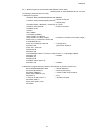
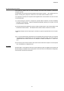
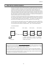
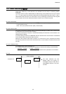
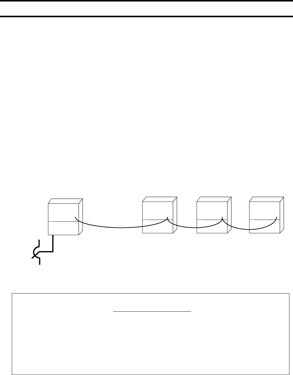
<Conceptual illustration>
Master (60Hz)
Slave 1 (50Hz)
Slave 2 (40Hz)
Slave 3 (30Hz)
VF-S11
VF-S11 VF-S11 VF-S11
A
nalog input
* A RS485 communication converter unit (RS4001Z,
RS4002Z or RS4003Z) will be needed to control multiple
inverters on the network.