


E6581222
38
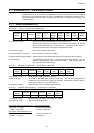
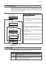
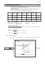
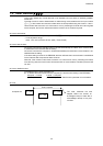
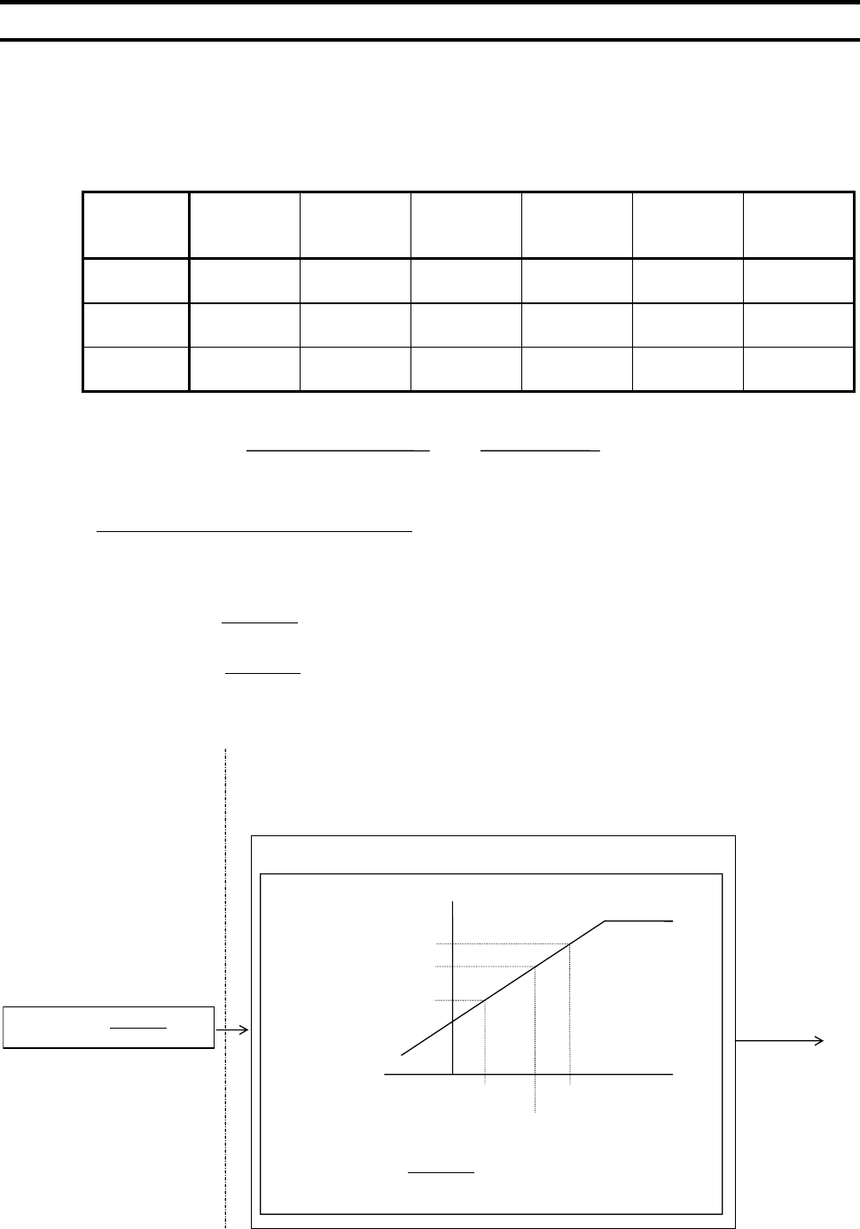
6.1. Speed proportional control
Various inclinations can be set by frequency point setting.
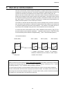
The frequency command value on the slave side during inter-drive communication can be expressed
by the following formulas.
If inter-drive communication is not selected (=), point conversion is not performed.
Point conversion is performed only when the command “S” is received.
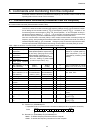
(Ex.) < unit > Frequency unit: 1=0.01(Hz), point setting unit: 1=0.01%
Maximum
frequency
()
Point 1
setting
()
Point 1 fre-
quency
()
Point 2
setting
()
Point 2
frequency
()
Frequency
(Fc)
Master (Fc) 100.00Hz
(10000)
50.00Hz
(5000)
Slave 1 100.00Hz
(10000)
0.00%
(0)
0.00Hz
(0)
100.00%
(10000)
90.00Hz
(9000)
45.00Hz
(4500)
Slave 2 100.00Hz
(10000)
0.00%
(0)
0.00Hz
(0)
100.00%
(10000)
80.00Hz
(8000)
40.00Hz
(4000)
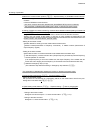
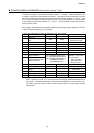
Sending data from the master:
Master send fc(%) = = = 5000 = 50%
Slave frequency Command(Hz)=
1(F811) point - 2(F814) Point
F812)frequency( 1 Point - F813)frequency( 2 Point
x (Master command (%) - Point 1(F811)) + Point 1 frequency(F812)
By the point conversion process,
Hz454500005000
010000
09000
Hzfc:1 Slave ==)−(×
−
−
=)(
Hz404000005000
010000
08000
Hzfc:2 Slave ==)−(×
−
−
=)(
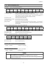
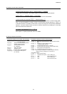
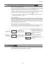
Diagram of speed proportional control
01000
FHMaster
FC Master
data
=
sendMaster ×
Point conversion
2-F811)+F81
F811F813
F812F814
(%) command Master((Hz) command Slave ×
−
−
=
Slave command (Hz)
Master command (%)
(%
Master command (%)
<Outside>
<Inverter’s internal computation>
(Note)fc=frequency reference, FH=Maximum frequency
Slave command (Hz)
Master side fc 10000
Master side FH
5000 10000
10000