


E6581222
53
8.3. Control of input/output signals from communication
The input terminals, output terminals, analog input and output signals of the inverters can be con-
trolled by communications.
Terminal Output Data (FA50)
The output terminals on the inverters can be controlled directly by communications.
Before controlling them, select Function Number 38 to 41 in Output Terminal Function Selection
(
- , ,). Set data (0 or 1) can be output to the output terminals by
setting data of Bit 0 and Bit 1 of terminal output data (FA50) by communications.
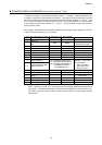
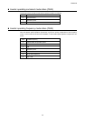
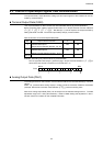
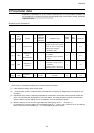
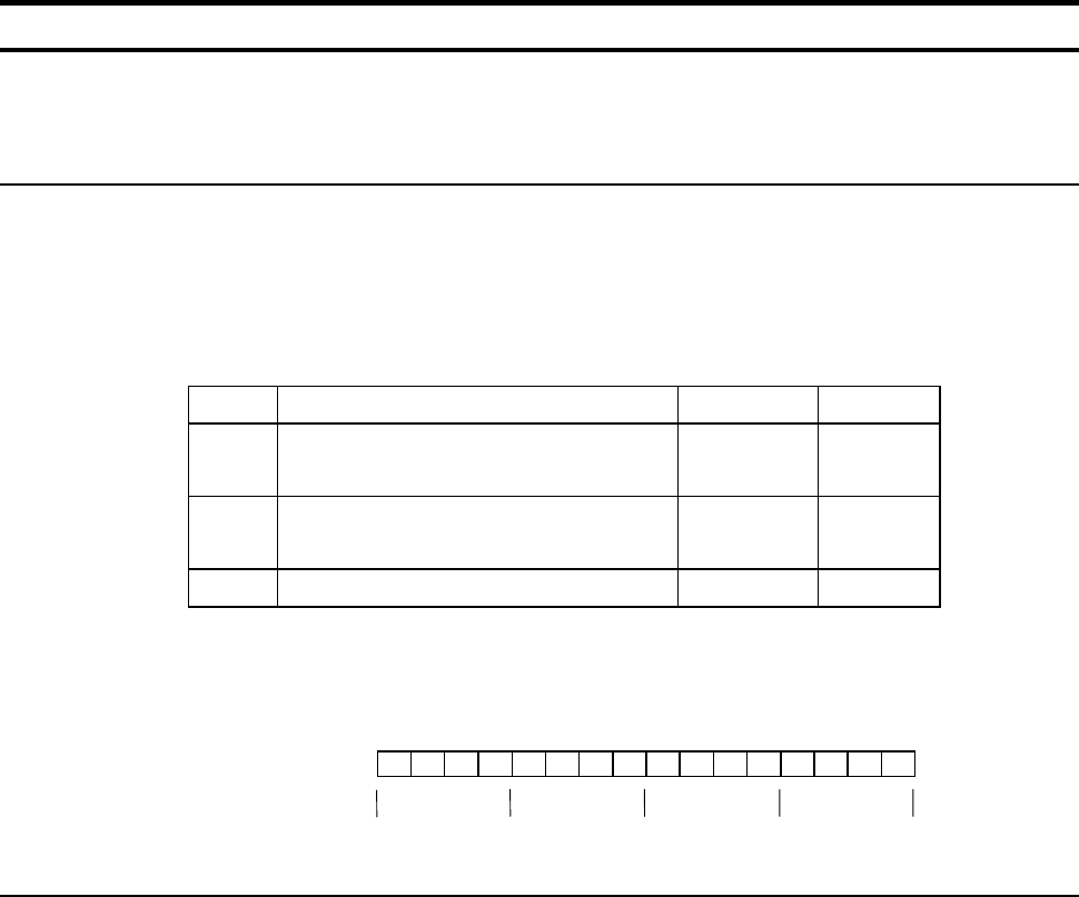
Data construction of Terminal Output Data (FA50)
Bit Output Terminal Function 0 1
0 Specified data output 1
(Output terminal selection Number : 38, 39)
OFF ON
1 Specified data output 2
(Output Terminal Selection Number : 40, 41)
OFF ON
2 to 15
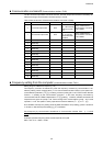
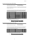
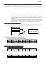
Example : Controlling only Terminal OUT1 by communication
Set “38” (specified data output 1 [positive logic]) in Output Terminal Selection 1 (
) in
advance and set “0001H” in FA50 to turn Terminal OUT1 on.
BIT15 BIT0
0000000000000001
Analog Output Data (FA51)
The analog terminals on the inverters, such as Terminal FM can be controlled directly by communi-
cations.
Select “18” (communication analog output) in Analog Terminal Connection Selection Parameters
(example: FM terminal connection meter selection [
]) before controlling them.
Data set in Analog Output Data (FA51) can be output from the selected analog terminal. The data
adjustment range is 0 to 1023 (10bit resolution) . Refer to “Meter Setting and adjustment” in the in-
struction manual for inverters for the complete information.
FA50:
100
0