Chapter 4: Powerline
At factory default powerline settings, the TPL-310AP 200Mbps Powerline AV Wireless N Access
Point (or other TRENDnet HomePlug® AV powerline adapter models TPL-303E, TPL-304E, TPL-305E,
TPL-401E) can be installed into any room in your home or small office with a wall power outlet, without
the need for additional software or configuration. Assuming the TRENDnet HomePlug® AV powerline
adapters are at factory default settings, to create a powerline network using the TPL-310AP and
another TRENDnet HomePlug® AV powerline adapter, simply plug one of the powerline adapters into a
wall power outlet in one room and plug the other powerline adapter into an available wall power
outlet in another room to establish connectivity between the two rooms.
In order to share Internet connectivity through your powerline adapters, it is ideal to install at
least one powerline adapter in the room where your modem and router are located and connect the
powerline adapter to one of your router’s LAN ports via Ethernet network cable. Any additional
powerline adapters that are installed and connected in other rooms will then share Internet
connectivity through your router. Once the powerline adapters are connected to each other through
the electrical system, any additional devices such as computers or network appliances (e.g. Game
Console, Blu-ray player, IP Set Top Box, network enabled TV, etc.) connected to any of your powerline
adapters via Ethernet can then communicate to each other as well as share Internet connectivity
through your router.
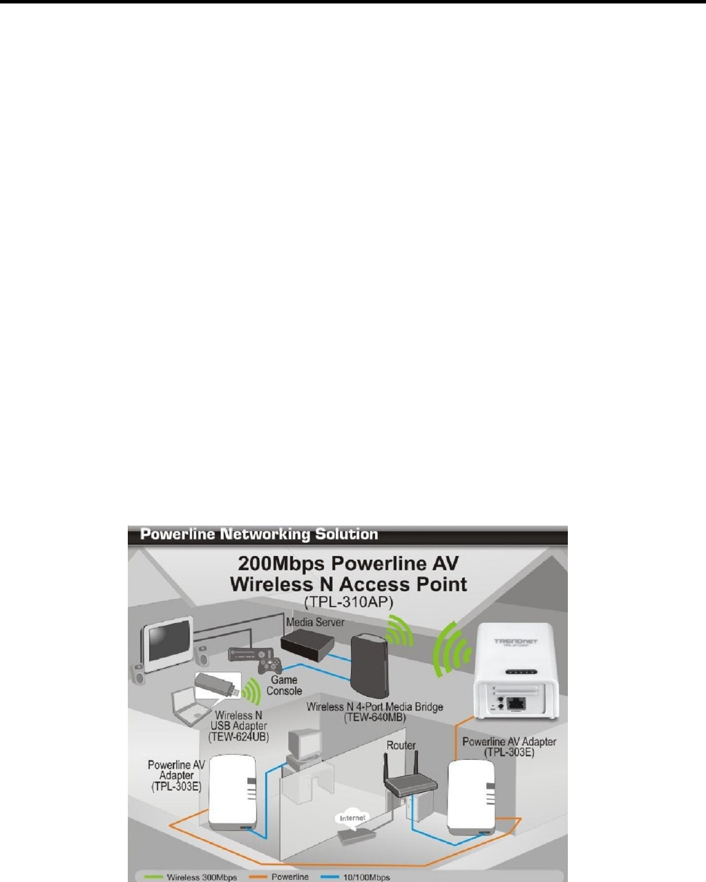
The installation diagram shows a typical setup of the TPL-310AP extending your wireless network connectivity to another room when
bridged with two additional powerline adapters, in this case, the TRENDnet TPL-303E. One TPL-303E is installed in the room with the rou-
ter and modem which will allow for Internet connectivity when connected through powerline. Any additional powerline adapters
connected will then be able to provide Internet connectivity to the other rooms. The orange line represents the powerline connectivity es-
tablished through your home’s electrical system and the blue lines represent Cat. 5, 5e, 6 Ethernet connectivity to your network enabled
appliances such as a computer, router, or IP set top box connected to your television. The green lines represent the wireless connectivity
from your wireless device (e.g. laptop computer, media bridge, etc.) to the TPL-310AP.


