


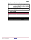
ML403 Board Information
XAPP979 (v1.0) February 26, 2007 www.xilinx.com 11
R
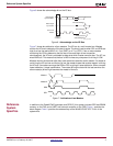
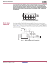
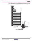
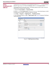
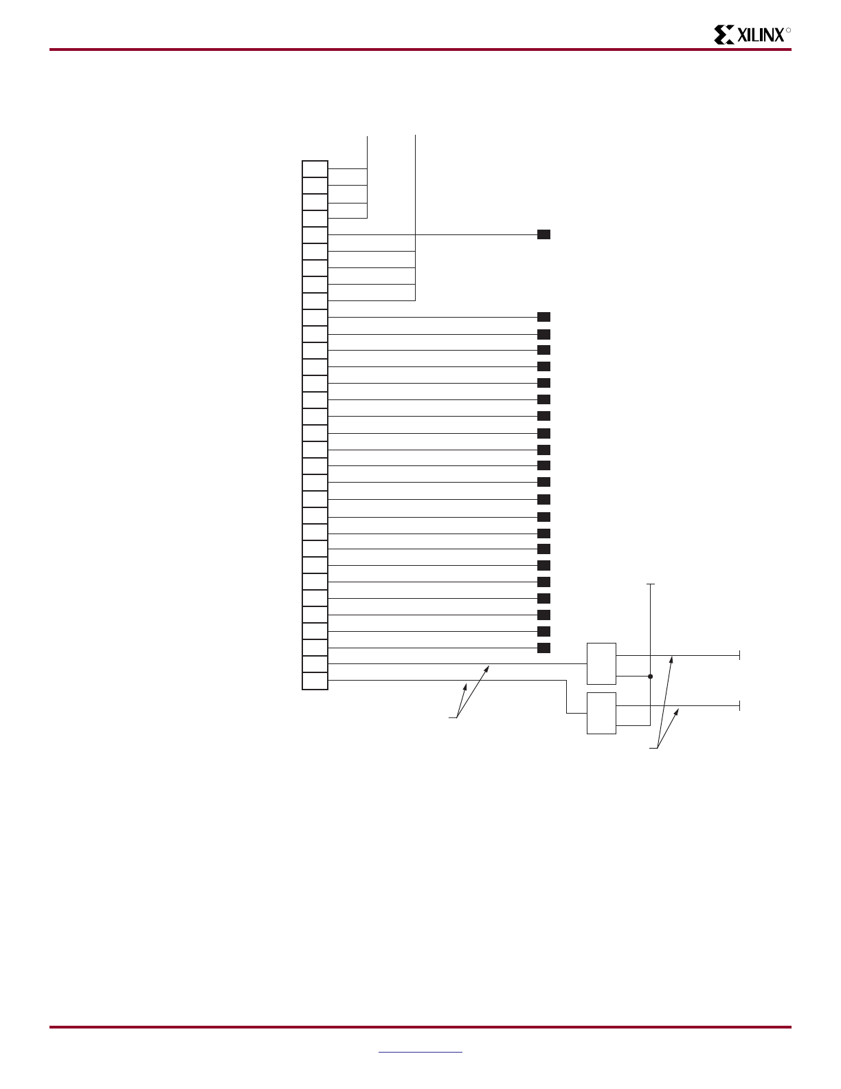
If additional IIC devices are connected to the bus via the expansion header as shown in
Figure 13, insert additional pull-up resistors on the external signals connected at pins 31 and
32. The resistor values are dependent on the voltage.
Figure 13: Expansion Header
NC
FPGA_PROM_CPLD_TMS
FPGA_PROM_CPLD_TCK
EXPANSION_TDO
CPLD_TDO
GPIO_LED_N
GPIO_SW_N
GPIO_LED_C
GPIO_SW_C
GPIO_LED_W
GPIO_SW_W
GPIO_LED_S
GPIO_SW_S
GPIO_LED_E
GPIO_SW_E
GPIO_LED_0
GPIO_LED_1
GPIO_LED_2
GPIO_LED_3
NC
NC
10
11
12
13
14
15
16
17
18
1
2
3
4
5
6
7
8
9
19
20
21
22
23
24
25
26
27
28
29
30
31
32
IIC_SCL
VCC2V5
Level
Translation
MOSFETs
External pullups
connect here
Internal pullups
connect here
IIC_SDA
NC
HDR 1 X 32
J3
X979_13_01
2