


Using ChipScope with OPB IIC
XAPP979 (v1.0) February 26, 2007 www.xilinx.com 19
R
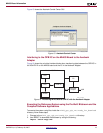
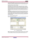
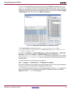
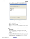
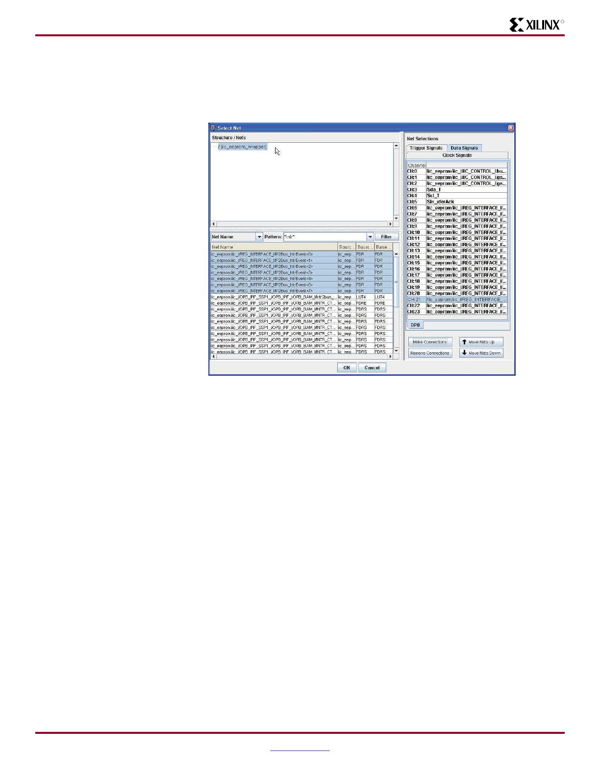
5. Figure 23 shows the GUI for making net connections. Click Next to move to the Modify
Connections window. If there are any red data or trigger signals, correct them. The Filter
Pattern can be used to find net(s). As an example of using the Filter Pattern, enter intr in the
dialog box to locate interrupt signals. In the Net Selections area, select either Clock, Trigger,
or Data Signals. Select the net and click Make Connections.
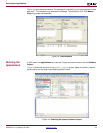
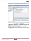
7. Click Insert Core to insert the core into iic_eeprom_wrapper.ngo. In the
ml403_ppc_opb_IIC/implementation directory, copy iic_eeprom_wrapper.ngo to
iic_eeprom_wrapper.ngc.
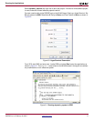
8. In XPS, run Hardware → Generate Bitstream and Device Configuration → Download
Bitstream. Do not rerun Hardware → Generate Netlist, as this overwrites the
implementation/iic_eeprom_wrapper.ngc produced by the step above. Verify that the
file size of the opb_iic_wrapper.ngc with the inserted core is significantly larger than the
original version.
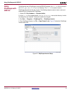
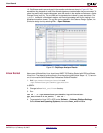
9. Invoke ChipScope Pro Core Analyzer by selecting
Start → Programs → ChipScope Pro → ChipScope Pro Analyzer
Click on the JTAG chain icon located at the top left of Analyzer GUI. Verify that the message in
the transcript window indicates that an ChipScope ICON is found.
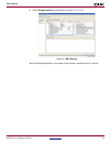
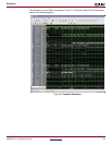
10. The ChipScope Analyzer waveform viewer displays signals named DATA*. To replace the
DATA* signal names with the signal names specified in ChipScope Inserter, select File →
Import and enter iic.cdc in the dialog box.
Figure 23: Making Net Connections in ChipScope Inserter
X979_23_012907