


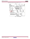

Reference System Specifics
XAPP979 (v1.0) February 26, 2007 www.xilinx.com 8
R
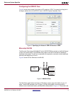
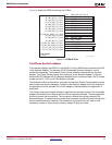
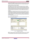
Configuring the OPB IIC Core
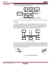
Figure 8 shows how to specify the values of IIC generics in EDK. To access the dialog box in
the figure, double click on the OPB IIC core in the EDK System Assembly View..
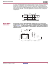
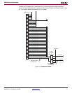
Microchip 24LC04
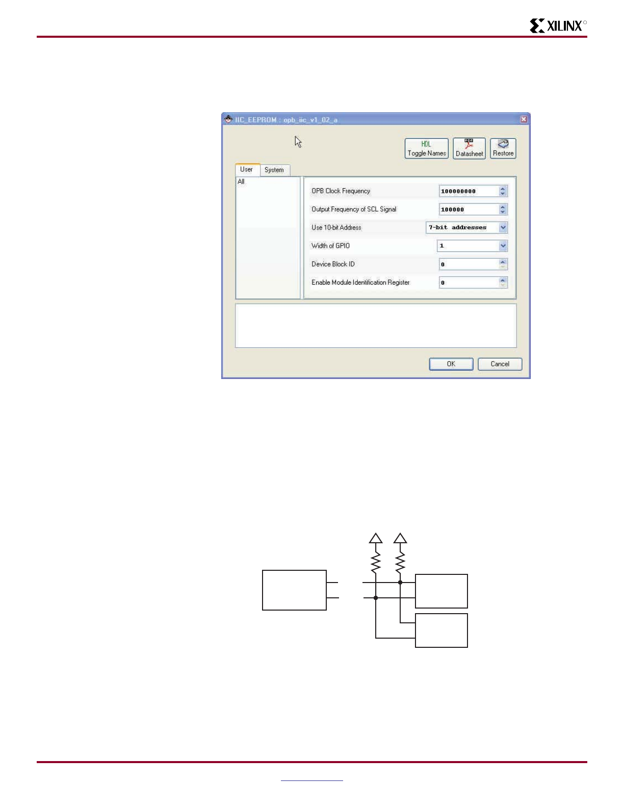
The Microchip Technology 24LC04B-I/ST with 4-KB EEPROM is provided on the ML403 board
to store non-volatile data. The EEPROM write protect is tied off on the board to disable its
hardware write protect. The IIC bus is extended to the expansion connector to allow additional
devices to be added to the IIC bus.
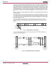
Figure 9 shows IIC Bus Devices on the ML403.
Figure 9: ML403 IIC Bus
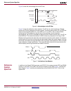
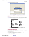
The 24LC04 is organized as two blocks of 256 bytes. It has a page write buffer of up to 16
bytes. The 24LC04 operates as an IIC slave. The 24LC04 accepts a control byte which
contains control code, block select, and Read/Write fields shown in Figure 10. The control code
Figure 8: Specifying the Values of OPB IIC Generics in EDK
X979_08_012907
XC4VSX12
FPGA
Microchip
24LC04B
I/O
Expansion
Header
X979_09_022307
SCL
SDA