


Simulation
XAPP979 (v1.0) February 26, 2007 www.xilinx.com 24
R
command from the command prompt:
impact -batch etc/download.cmd
12. Invoke XMD. From the ml403_ppc_opb_iic/linux directory, enter the following
commands in the XMD window.
rst
dow arch/ppc/boot/images/zImage.initrd.elf
con
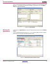
13. View the output in the HyperTerminal window. Login as root. Enter cd / and ls -l to
view the contents of the mounted Linux partition.
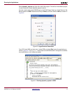
14. An alternative to downloading the Linux kernel executable is to load it into CompactFlash.
The file used uses an ace file extension. To generate an ace file, run the command below
from the ml403_ppc_opb_iic directory.
xmd -tcl /genace.tcl -jprog -hw ./implementation/system.bit -ace
./implementation/ace_system_hw.ace -board ML403
Copy the ace file to a 64-512 MB CompactFlash (CF) card in a CompactFlash reader/writer.
Remove the CF card from the CF reader/writer and insert it into the CompactFlash slot (J22) on
the ML403 board. Power up the board.
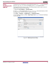
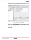
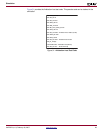
Simulation The ml403_ppc_opb_iic/simulation directory contains waveform log file, opb_iic.wlf, for
IIC transactions discussed in this section.
The opb_iic.wlf files are easily loaded into the Modeltech simulator using the File → Open
command, specifying the *.wlf file type.
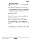
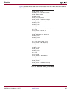
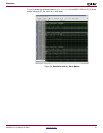
The OPB IIC core has two Finite State Machine (FSM). The clock FSM has IDLE, START,
SCL_LOW_EDGE, SCL_LOW, SCL_HIGH_EDGE, SCL_HIGH, STOP_WAIT states. The main
FSM has IDLE, HEADER, ACK_HEADER, RCV_DATA, XMIT_DATA, ACK_DATA, and
WAIT_ACK states.
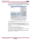
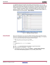
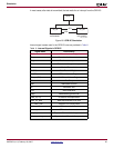
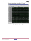
Figure 28 shows the two OPB IIC cores in the simulation. The simulation is a Bus Functional
Model simulatation of two OPB IIC cores. The IIC cores with addresses 20 and AA are
designated iic_20 and iic_AA, with C_BASEADDR of 0xE0000000 and 0xE1000000,
respectively. Both cores connect to SCL and SDA. The stimuli is provided by writing the OPB
IIC registers.
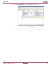
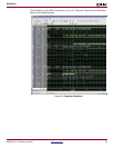
As an example
write cr 41
enables the OPB IIC and sets the General Call enable. The address determines which OPB IIC
is the target of the write, with 0xE0000100 for iic_20 and 0xE1000100 for iic_AA. It may be
useful to consult the register map in Table 2 and the control (Table 3), status (Ta ble 4 ), and
interrupt status register (Ta ble 5 ) definitions.