


Chapter 7 Interfaces
ZyWALL 110/310/1100 Series User’s Guide
160
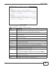
If computer B responds to computer A, bridge X records the source address 0B:0B:0B:0B:0B:0B
and port 4 in the table. It also looks up 0A:0A:0A:0A:0A:0A in the table and sends the packet to
port 2 accordingly.
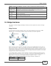
Bridge Interface Overview
A bridge interface creates a software bridge between the members of the bridge interface. It also
becomes the ZyWALL’s interface for the resulting network.
Unlike the device-wide bridge mode in ZyNOS-based ZyWALLs, this ZyWALL can bridge traffic
between some interfaces while it routes traffic for other interfaces. The bridge interfaces also
support more functions, like interface bandwidth parameters, DHCP settings, and connectivity
check. To use the whole ZyWALL as a transparent bridge, add all of the ZyWALL’s interfaces to a
bridge interface.
A bridge interface may consist of the following members:
• Zero or one VLAN interfaces (and any associated virtual VLAN interfaces)
• Any number of Ethernet interfaces (and any associated virtual Ethernet interfaces)
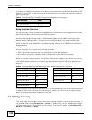
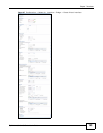
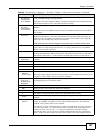
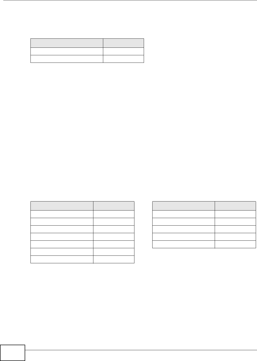
When you create a bridge interface, the ZyWALL removes the members’ entries from the routing
table and adds the bridge interface’s entries to the routing table. For example, this table shows the
routing table before and after you create bridge interface br0 (250.250.250.0/23) between lan1
and vlan1.
In this example, virtual Ethernet interface lan1:1 is also removed from the routing table when lan1
is added to br0. Virtual interfaces are automatically added to or remove from a bridge interface
when the underlying interface is added or removed.
7.8.1 Bridge Summary
This screen lists every bridge interface and virtual interface created on top of bridge interfaces. If
you enabled IPv6 in the Configuration > System > IPv6 screen, you can also configure bridge
interfaces used for your IPv6 network on this screen. To access this screen, click Configuration >
Network > Interface > Bridge.
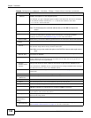
Table 55 Example: Bridge Table After Computer B Responds to Computer A
MAC ADDRESS PORT
0A:0A:0A:0A:0A:0A 2
0B:0B:0B:0B:0B:0B 4
Table 56 Example: Routing Table Before and After Bridge Interface br0 Is Created
IP ADDRESS(ES) DESTINATION IP ADDRESS(ES) DESTINATION
210.210.210.0/24 lan1 221.221.221.0/24 vlan0
210.211.1.0/24 lan1:1 230.230.230.192/26 wan
221.221.221.0/24 vlan0 241.241.241.241/32 dmz
222.222.222.0/24 vlan1 242.242.242.242/32 dmz
230.230.230.192/26 wan 250.250.250.0/23 br0
241.241.241.241/32 dmz
242.242.242.242/32 dmz