


Galaxy GHDX2-2430S/R-24F4D Installation and Hardware Reference Manual
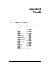
C-2 Pinouts
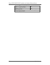
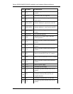
Pin Pin Name Pin Description
1
V
EET
Transmitter ground (common with receiver
ground)
2
T
FAULT
Transmitter fault; not supported
3
T
DIS
Transmitter disable; laser output disabled on
high or open
4
MOD_DEF(2) Module definition 2; data line for serial ID
5
MOD_DEF(1) Module definition 1; clock line for serial ID
6
MOD_DEF(0)
Module definition 0; grounded within the
module
7
Rate Select No connection required
8
LOS
Indicates loss of signal; logic 0 indicates
normal operation
9
V
EER
Receiver ground (common with transmitter
ground)
10
V
EER
Receiver ground (common with transmitter
ground)
11
V
EER
Receiver ground (common with transmitter
ground)
12
RD- Receiver inverted DATA out; AC coupled
13
RD+ Receiver non-inverted DATA out; AC coupled
14
V
EER
Receiver ground (common with transmitter
ground)
15
V
CCR
Receiver power supply
16
V
CCT
Transmitter power supply
17
V
EET
Transmitter ground (common with receiver
ground)
18
TD+
Transmitter non-Inverted DATA in 100 ohm
termination between TD+ and TD-; AC
coupled thereafter
19
TD- Transmitter inverted DATA in. See TD+
20
V
EET
Transmitter ground (common with receiver
ground)