


Chapter 2 Hardware Installation
Hardware Installation
2-3
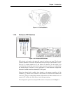
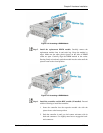
Step 4. Verification of hard drive installation into the drive trays.
Although SATA-II interface hard drives have been installed into drive
trays for you, follow this procedure to replace individual hard drives.
(See Section 2.7)
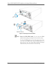
Step 5. Install the drive trays into the enclosure. Note that the drive trays
used in single- or redundant-controller subsystems are different. Make
sure not to mix the drive trays. A redundant-controller subsystem
requires the MUX boards on its drive trays.
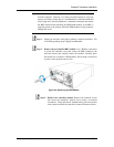
Step 6. Connect the cables. Use the supplied power cords to connect the
subsystem to power mains. It is recommended to connect power cords
to separate and independent power sources, e.g., UPS systems, for
higher redundancy. Make sure your subsystem is electrically
grounded.
It is also recommended to use the included cable clamps to prevent
accidental disconnection of the power cords. Use separately purchased
Fibre Channel optical cables and transceivers to connect the host ports
to your Fibre Channel storage network or directly to the host
computers. (See Chapter 4)
SAS expansion JBODs come with SAS 4x, wide link cables.
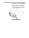
Step 7. Power up. Once all of the components have been properly installed
and all the cables properly connected, the subsystem can be powered
up and the RAID array configured. (See Chapter 4)
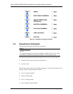
2.4.1 Installation Procedure Flowchart
Figure 2-1 shows a flowchart of the installation procedure. As you complete each step,
check off the “Done” box on the right. Please use this flowchart in conjunction with the
instructions that follow.