


Galaxy GHDX2-2430S/R-24F4D Installation and Hardware Reference Manual
Introduction
1-6
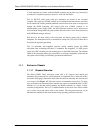
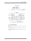
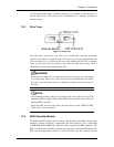
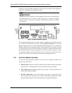
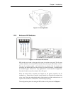
Each RAID controller module comes with four (4) SFP host ports, two (2) RS-232C
(audio jack) serial ports, one (1) RJ-45 Ethernet connector and status-indicating LEDs
located on its rear-facing faceplate.
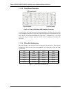
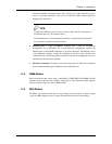
1.1.1.6 The Backplane Board
An integrated backplane board receives disk drives on the front end and connects the
RAID controller, cooling, and PSU modules on the other side. The PCB board provides
logic level signals and low voltage power paths. It contains no user-serviceable
components.
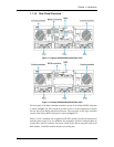
1.1.1.7 Subsystem Rack/Cabinet Installation
The subsystem chassis has pre-drilled screw holes for rackmounting. Separately
purchased, independently installed rackmount rails are available for rack or cabinet
installation.
The slide rails come with their own printed copies of installation guide.
1.2. Subsystem Components
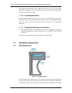
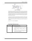
1.2.1 LCD Keypad Panel
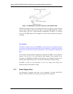
Figure 1-7: LCD Keypad Panel
The LCD keypad panel consists of an LCD display with push buttons and LEDs that
indicate array statuses. The LCD panel provides full access to all RAID configurations
and monitoring options. After powering up the subsystem, the initial screen will display