


Galaxy GHDX2-2430S/R-24F4D Installation and Hardware Reference Manual
Introduction
1-10
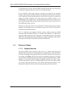
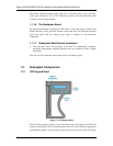
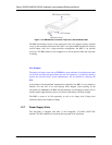
Figure 1-10: BBU Module, Controller Top Cover, and the Module Slot
The BBU functionality consists of two major parts. One is the charger circuitry mounted
on top of the controller main board. The other is an optional BBU module that contains
several battery cells. On a single-controller configuration, the BBU is an optional
accessory. The BBU module is hot-swappable so it can be replaced while the subsystem
is running.
New Feature:
The battery cell packs come with an EEPROM to record the date of installation and other
service data; and when the approximate one-year life expectancy is reached (by checking
against the real-time-clock), system administrators will be notified for replacing the
BBU.
In accordance with international transportation regulations, the BBU is only charged to
between 35% and 45% of its total capacity when shipped. After powering on the
subsystem (see Section 4.1) the BBU will automatically start charging its battery cells. It
usually requires approximately twelve (12) hours for the battery to be fully charged.
The BBU is aware of its life expectancy as well as its charge level. Charge level
awareness helps avoid frequent re-charge.
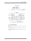
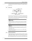
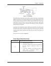
1.2.7 Power Supply Units
The subsystem is equipped with three (3) hot swappable, 1U-profile, 405W PSU
modules. The PSU modules are located on the rear panel of the subsystem.