


Galaxy GHDX2-2430S/R-24F4D Installation and Hardware Reference Manual
Introduction
1-8
contains no user-serviceable components. Only remove the controller when replacing a
faulty unit or installing/ the cache memory inside.
WARNING!
Although the RAID controllers are hot-swappable, the only time you should handle
the controller itself is to remove a failed controller, or to install and replace
memory modules. Unnecessary tampering with the RAID controller can damage
the controller.
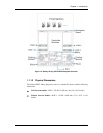
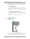
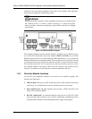
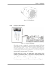
Figure 1-9: RAID Controller Faceplate
The controller faceplate provides external interfaces including four (4) SFP host ports,
two (2) RS-232C (audio jack) serial ports (labeled COM1 and COM2), one (1) RJ-45
Ethernet connector and six (6) status-indicating LEDs (labeled from 1 to 6), one Restore
Default LED and the associated push button. The controller main circuit board is housed
in a metal canister and can only be seen after the controller is removed from the chassis.
The controller canister has two (2) ejection levers that can be used to retrieve or secure
the controller module to the chassis. These levers are secured to the enclosure chassis
using two (2) retention screws through the screw holes underneath each lever.
1.2.4 Controller Module Interfaces
All host I/O and management interfaces are located on the controller faceplate. The
interfaces are listed below.
SFP host ports: Host ports are SFP sockets that receive 4Gb/s interface fiber optical
transceivers. It is recommended to use only certified transceivers and cables.
SAS expansion port: The SAS expansion port provides a 12Gb/s wide link to the
Galaxy series expansion JBODs.
RS-232C (Audio Jack): All controller modules come with two (2) RS-232C (audio
jack) serial ports The serial ports can be used for establishing a management session
through terminal emulation and uninterruptible power supply (UPS) support.