


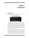

Chapter 1: Introduction
1-7
the subsystem model name. A different name can be assigned for the subsystem or
specific logical drives. This enables ease of identification in a topology consisting of
numerous arrays.
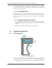
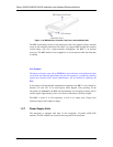
1.2.2 Drive Trays
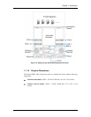
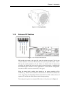
Figure 1-8: Drive Tray
The subsystems’ twenty-four (24) drive trays accommodate separately purchased,
standard 1-inch pitch, 3.5-inch disk drives. The drive bays are accessed through the front
of the enclosure. Two (2) LEDs on each tray bezel indicate the disk drive’s operation
status. A rotary bezel lock on each drive tray secures the hard drive in place, while a
release button can be used to open the front bezel.
WARNING!
Be careful not to warp, twist, or contort the drive tray in any way (e.g., by dropping
it or resting heavy objects on it). The drive tray has been customized to fit into the
drive bays in the subsystem and if it is deformed or altered it may not fit into the
drive bay.
NOTE:
The redundant-controller subsystem is shipped with twenty-four drive trays with
multiplexer (MUX) adapter boards. These MUX boards provide access routes for
different RAID controllers.
Please DO NOT use drive trays from a previous Galaxy model, GHDX-7376R6-
24F2D. They are not compatible.
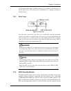
1.2.3 RAID Controller Module
The RAID controller module contains a main circuit board and a daughter card providing
additional interface connectors, management and host interfaces, and a preinstalled
512MB DDR RAM DIMM. The subsystem comes standard with BBU protection. The
BBU is installed in the module bay located at the top center of the controller module. The
BBU can be independently inserted or removed. Please note: The controller module